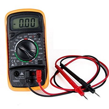
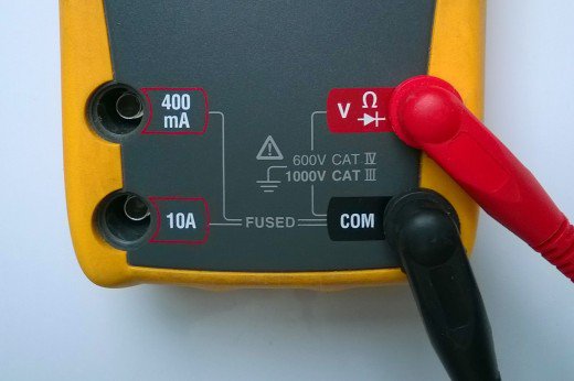
Multi-meter


Those are two pictures of multi-meters.
The standard multi-meter will have a dial with various settings on. Those settings are subdivided into categories such as AC volts, DC volts, current and resistance.
Within each category there is typically between 2 and 6 selectable ranges, dependant upon how large the reading is. This allows for more accurate readings where needed.
Note that on the connections there is a pair of sockets for current. This is because those have a fuse in to stop idiots from blowing up the meter. There are two overall ranges for the current, one that is limited (in this case) to 400mA, and a second bigger one for 10A range.
To measure the current in a circuit, the metre needs to be within the circuit, such that the current flow through the circuit is also going through the metre. The metre is placed in SERIES with the component(s) being monitored.
To measure a voltage, you measure across a component or power supply. You measure the voltage in PARALLEL to the component(s) being monitored.
Along with the standard multi-meter we do have several units which look similar that will only measure temperature, and another that accurately measures inductance, resistance and capacitance (this one is not leant out without an operator!!).
Oscilloscope

This is an oscilloscope. They sometimes get referred to as a 'scope to make the pronunciation easier. (From here on, they will be referred to as scope(s).)
There are multiple functions that a scope can achieve. The simplest is using a probe or cable and connecting it up to a signal generator. This is useful for setting up the generator and confirming that you are getting the correct signal out. It is achieved by connecting the BNC connector in the front of this unit to a probe or cable, and likewise to a suitable connection at the other end.
Once both units are turned on, there should be a line going across the screen of the scope. If not, then there may be some issues.
| Issue |
Solution |
| No image on display, no lights. |
Check that the power is getting to the unit and ensure unit is switched on. |
| Display on, no lines. |
Check that the channel is on. Is there a button saying on/off in the right hand side of the unit near the plug?
This can be in the box above the socket.
On the unit pictured it is the 'ch1 menu' button.
|
| Line present, no movement |
Check that the signal is going to the correct channel. |
| Line present, no movement, correct channel. |
In the horizontal axis, there is a button labelled 'normal' or 'auto'. Press this. |
| Very slight movement (vertically). |
Ensure that the voltage scale is appropriate for the incoming signal. This setting is typically controlled by the dial closest to the socket being used. |
| Slow ramp for a sine wave. |
Ensure that the horizontal axis relates to the frequency appropriately. Aim for multiple waveforms on the display (typically between 2 and 5). |
One common issue that people often come to us about is that their signal appears to be approximately 50% or 200% of what it should be. This can be caused by a very small, very annoying button labled 50Ω (or 50ohm) on scopes. This feature is because the majority of BNC cables used in the chemistry (and elsewhere)use 50Ω cable. The reason that this style is classed this, is because when the user sends down a fast signal, unless there is a 50Ω resistor in series with the start, and a 50Ω to ground in parallel to the furthest output connection, ringing will occur.