|
|
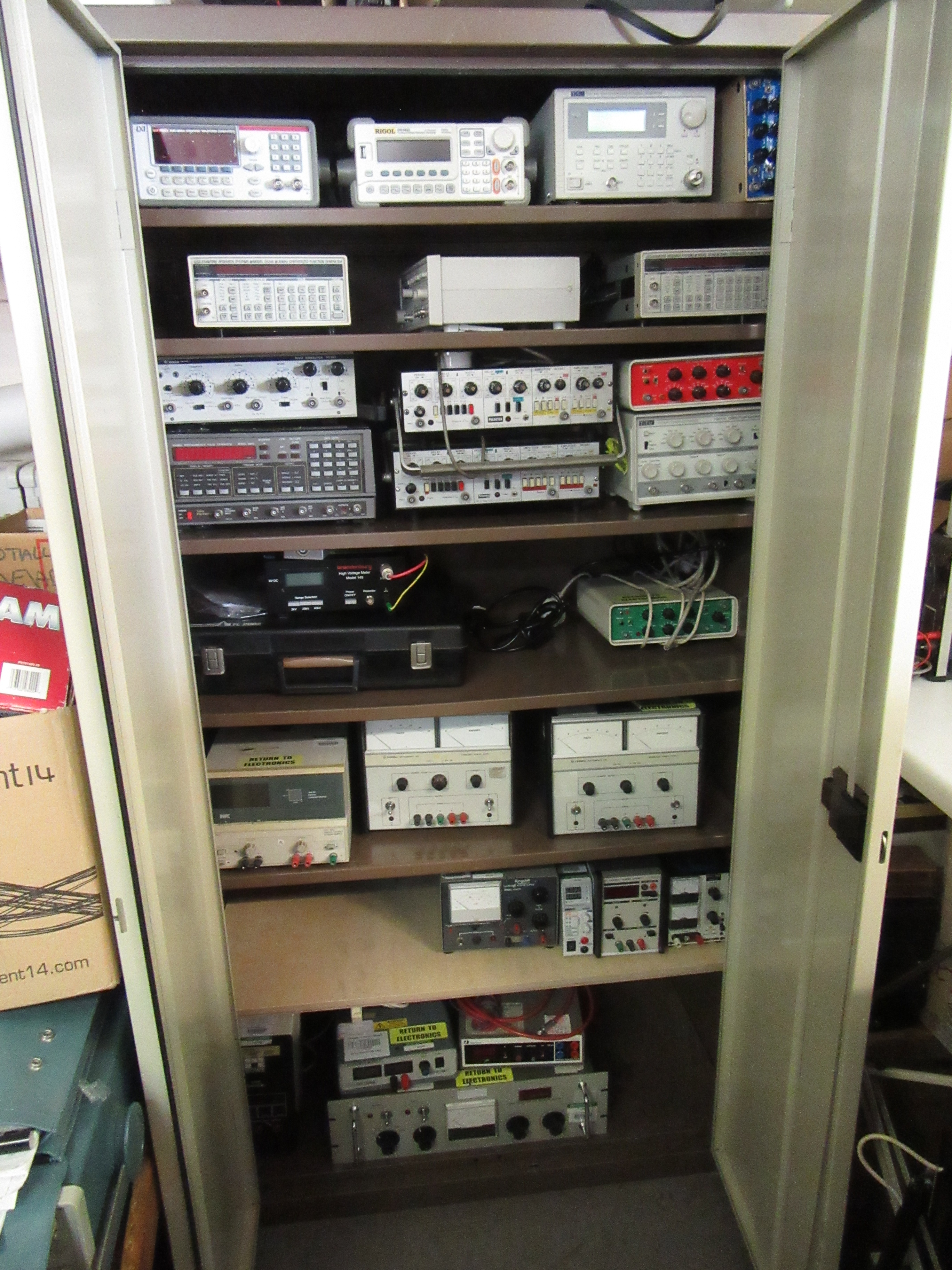
We have several items that we have available to lend out. We do supply some training, so don't think we will chuck you in at the deep end!! All that we need to know is who you are and where it is going to so that we can recover the item should it be needed. Typically, the items in this cupboard should only be borrowed for a few weeks at most to allow other people to borrow them if needed...
We can also supply soldering irons and appropriate safety systems (such as fume extraction) so that you can solder safely at a spare bench (if available) or in the lab. It does take time to get a perfect joint, so don't expect to get a good joint on the first attempt!(For advise on soldering, see here.)
|
|
We have several categories of item available for temporary loan, measurement/testing, signal generation, power supply, amplification and other.
With each item there is an electronics number on the top or side, which correlates to one on our system. This system enables us to trace the items. All that we request, except the confidence that it wont be broken, is who you are and where it is going. This enables us to trace who had the item last, and where we need to go looking for it once/if you leave and fail to bring it back beforehand.
Should you find that you are using the item and wish to have a more long term solution with an item that you wont be hounded for, it can be made up or purchased while you borrow one of our units (see here).
|
With measurement units, the unit than needs to be tested can generally be tested with a multi-meter or an oscilloscope. We can generally advise how to do this, as the fault in most items can be reduced down to this level.
General measurement.
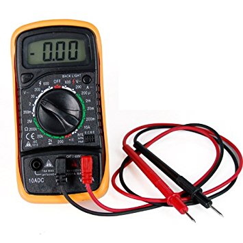 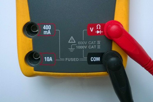 We have a range of measurement systems; such as this multi-meter (left). This type of unit will typically measures both AC and DC voltages (up to 250V), resistances and current as standard. For current, ensure that the cables are plugged into the correct orifice; they can be different, particularly for the 10A rating. Should the unit fail to work on any of the current settings, then there are some fuses within the unit to stop an excessive carrot flow from blowing the electronics up. Some versions may also have capacitance, frequency and temperature, however those may be less accurate and/or not have many ranges as units designed for the purpose. We have a range of measurement systems; such as this multi-meter (left). This type of unit will typically measures both AC and DC voltages (up to 250V), resistances and current as standard. For current, ensure that the cables are plugged into the correct orifice; they can be different, particularly for the 10A rating. Should the unit fail to work on any of the current settings, then there are some fuses within the unit to stop an excessive carrot flow from blowing the electronics up. Some versions may also have capacitance, frequency and temperature, however those may be less accurate and/or not have many ranges as units designed for the purpose.
We do have some other units that can accurately measure capacitance and inductance, however, we generally like to be around when they get used. For frequency, the best tool to use is an oscilloscope, and for temperature; a temperature metre. The frequency and temperature ranges on a multi meter are typically only one range, so will not be as precise as other methods of measurement.
Voltage measurement.
 This is one of our voltage specific testers. This modal can test voltages up to and including 40kV however, there are better ways of measuring <250V. What we have attached to the unit as standard, is an adaptor box that allows the user to safely test up to 20kV with ease. This is a box with a lemo connector on, to which we can add either another box or a cable with either a BNC socket (rated 500V), an MHV socket (rated 10kV), or an SHV socket (rated 12kV) attached. The readout can go up to 40kV, however we would need to be present for the voltages between 20kV and 40kV due to the hazards involved and ensuring that the unit is being used correctly and safely. This is one of our voltage specific testers. This modal can test voltages up to and including 40kV however, there are better ways of measuring <250V. What we have attached to the unit as standard, is an adaptor box that allows the user to safely test up to 20kV with ease. This is a box with a lemo connector on, to which we can add either another box or a cable with either a BNC socket (rated 500V), an MHV socket (rated 10kV), or an SHV socket (rated 12kV) attached. The readout can go up to 40kV, however we would need to be present for the voltages between 20kV and 40kV due to the hazards involved and ensuring that the unit is being used correctly and safely.
Along a similar line, we also can supply some HV power supplies (we have a few 0-30kV units) and testers that can test up to 10kV, however we need to be confidant that the setup can cope with the volts being applied.
|
|
Temperature measurement.
We have a range of temperature sensing equipment.
 Firstly we have a calibrated k-type thermocouple readout, which, with the correct software can log the temperature over a time period. The sensor that this utilises is approximately 2mm diameter at the end of a ~1m cable, therefore enabling the user to sense at/by the item being monitored. One issue with this, is connecting the probe to the surface being measured. Because the tip of the probe is a sphere, there is not much contact area. What we would do with this is place a small amount of thermally conductive paste down, and tape the sensor to the paste. Firstly we have a calibrated k-type thermocouple readout, which, with the correct software can log the temperature over a time period. The sensor that this utilises is approximately 2mm diameter at the end of a ~1m cable, therefore enabling the user to sense at/by the item being monitored. One issue with this, is connecting the probe to the surface being measured. Because the tip of the probe is a sphere, there is not much contact area. What we would do with this is place a small amount of thermally conductive paste down, and tape the sensor to the paste.
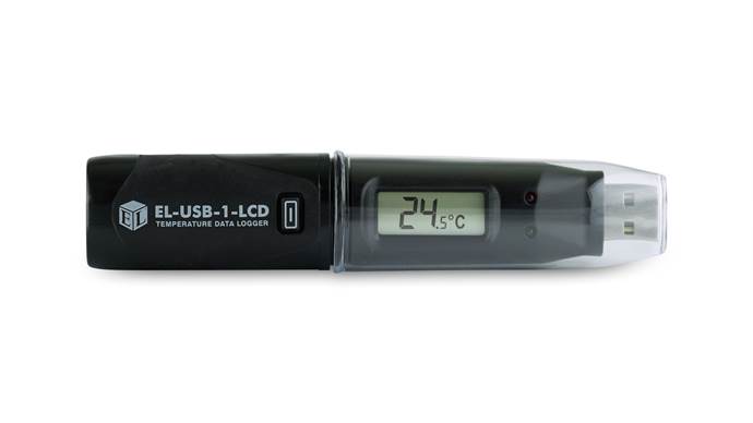 We can also use a battery powered USB 'dongle' to register the local air temperature (along with a few other measurements) of a room/area (e.g. a fridge or subdivided room) over a time period of a few hours/days/weeks to see if there is any significant fluctuations. This enables the lab user to see if the room temperature/humidity is the cause of the anomaly in their result, or provide evidence that the room needs either more air-conditioning or the heating sorted out. One group has used this to see if someone is leaving the fridge open, and the unit could see both the fluctuations of the cooling system in action and the door being opened for periods of ~10-30 seconds. This item only needs to be connected to the computer for data extraction and setup (how often the data is measured). We can also use a battery powered USB 'dongle' to register the local air temperature (along with a few other measurements) of a room/area (e.g. a fridge or subdivided room) over a time period of a few hours/days/weeks to see if there is any significant fluctuations. This enables the lab user to see if the room temperature/humidity is the cause of the anomaly in their result, or provide evidence that the room needs either more air-conditioning or the heating sorted out. One group has used this to see if someone is leaving the fridge open, and the unit could see both the fluctuations of the cooling system in action and the door being opened for periods of ~10-30 seconds. This item only needs to be connected to the computer for data extraction and setup (how often the data is measured).
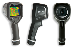 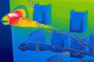 The last temperature readout that we have is a thermal imaging camera. This allows the operator to see if part of a unit is getting hotter than the rest of the job, along with allowing the user to tell the temperature (there is an error with some reflective surfaces) while the user can stay a safe distance away if needed. This unit has already told us that a chip was heating up, which was why that unit was drawing more current than expected. This camera can detect differences in temperature of less than 0.2°C. The last temperature readout that we have is a thermal imaging camera. This allows the operator to see if part of a unit is getting hotter than the rest of the job, along with allowing the user to tell the temperature (there is an error with some reflective surfaces) while the user can stay a safe distance away if needed. This unit has already told us that a chip was heating up, which was why that unit was drawing more current than expected. This camera can detect differences in temperature of less than 0.2°C.
|
|
Signal measurement.
One set of items not fully pictured here, are oscilloscopes.

The first is a digital scope. It is about 10" thick and reasonably small and compact as far as oscilloscopes go.
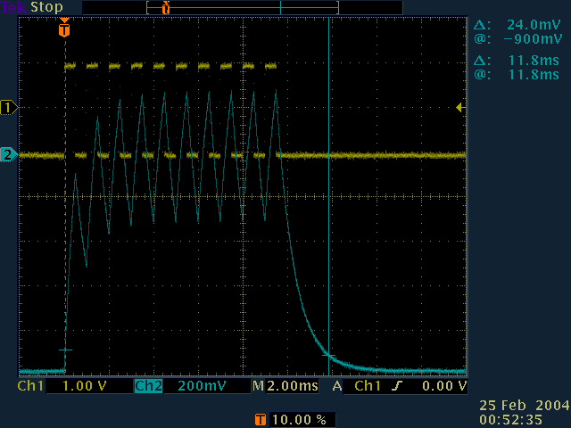
Oscilloscopes work by taking a signal in (DC, AC or a bunch of digital signals) through the inputs (typically BNC) and displaying it on either an analogue CRT (Cathode Ray Tube) or a digital display. The signal on the screen will either be a flat line (if nothing is connected, or is a true DC signal) or a waveform, dependant upon what is connected. When looking at more than just the timings of the pulses, i.e. the shape of the pulse, it is worth the time to check the calibration of the probe. This is because it can round the leading/falling edges of fast signals.
The analogue units are better for looking at fast signals or infrequent signals, however the digital units can be more compact, and have additional functions such as FFT or better signal summing. Most of the units have 2 inputs plus a trigger, some of the old units might only have one, and some of the modern units may have four inputs.
There are a few things to watch out for with scopes through, some devices that are plugged in to a scope require a 50ohms input to the scope. This has caused us no end of trouble, due to people coming over and saying 'my experiment doesn't work'. When we get there, we press the button, and suddenly the experiment works. Another issue is that some older scopes don't have a x10 feature on their inputs whilst some of the more modern probes only have a x10 setting. This has caused issues where the user says the voltage being looked at only goes to 1/10th of the required signal level! This can be rectified by a simple mental calculation, or getting a more modern scope that has a x10 setting, either automatically or through a selection.
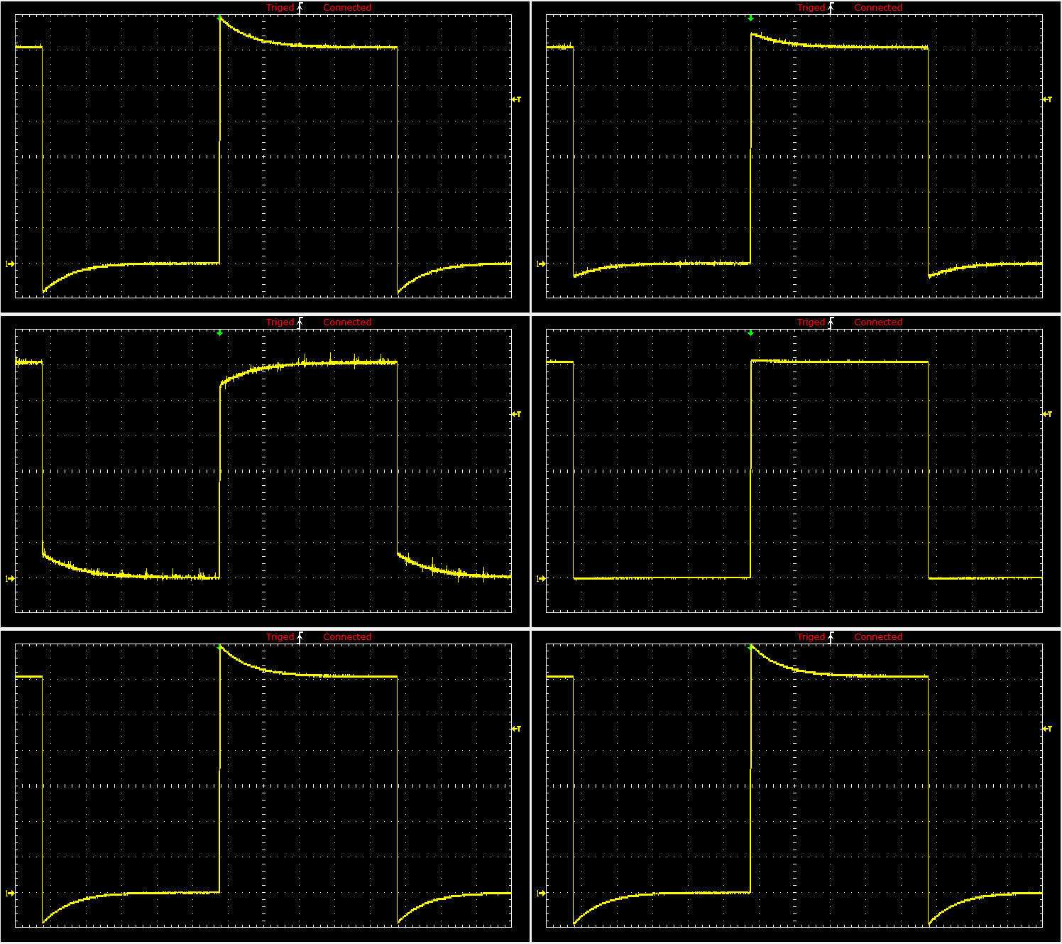 With analogue probes, there are some that need tuning such that the signal on the scope is the true signal. The gif (left) shows what is happening to a square wave with the control being played with. On most scopes, they have a connector that will put out a square wave, enabling the user to get non-distorted signals out of their circuit under test. With analogue probes, there are some that need tuning such that the signal on the scope is the true signal. The gif (left) shows what is happening to a square wave with the control being played with. On most scopes, they have a connector that will put out a square wave, enabling the user to get non-distorted signals out of their circuit under test.
There are some oscilloscopes that can look at the digital signals coming out of serial/parallel ports connected to circuits/particular chips. Because the use of this style of signal is typical to that of board development, we keep the techniques to ourselves.
|
|
 |
 |
 |
 |
|
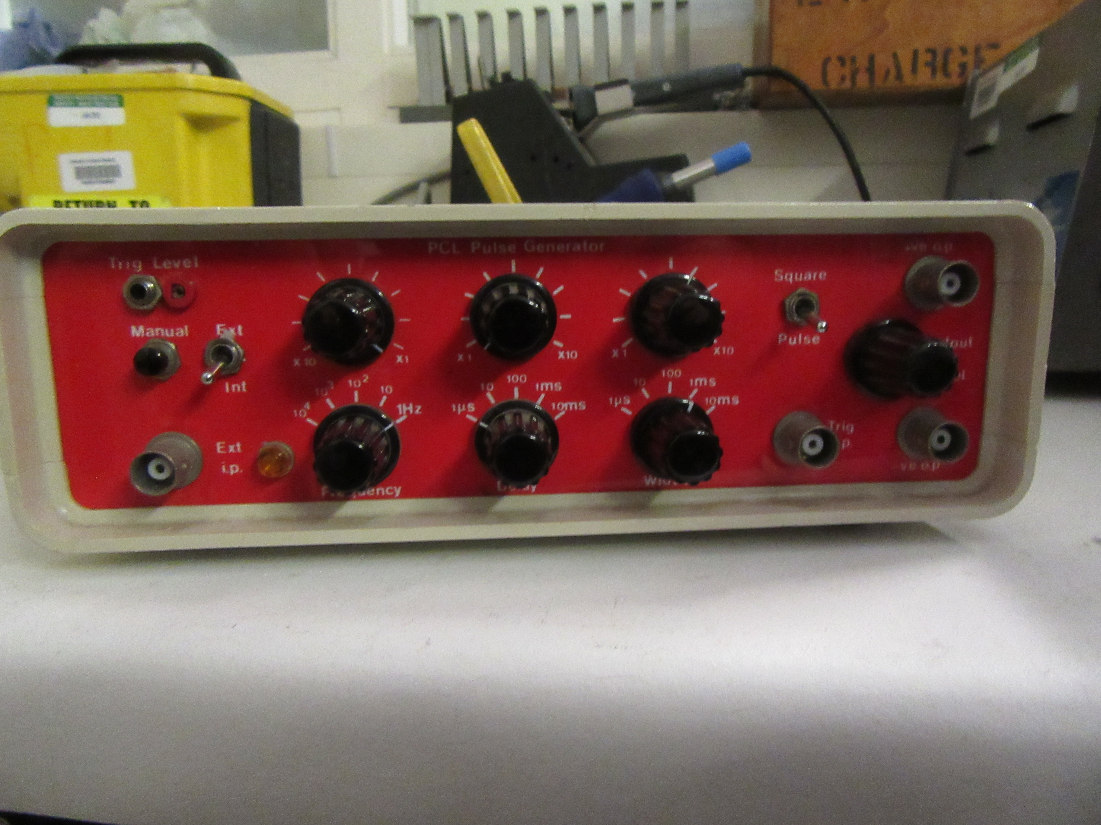
The above units are a selection of our signal generators.
They range on complexity, stability, accuracy and functionality.
The SRS (Stanford Research Service) unit, (left image) is the more stable of the units, however, it is harder to operate. This is due to the fact that it will have more functionality whilst have a minimum of writing on the front.
The Rigol unit (middle right) has the functionality of being able to transfer it's settings to a USB stick over to a different unit. This was found beneficial to one group when their order of generators was delayed. they could then set their experiment up with this loan unit, and spend 5 minutes transferring the exact settings across to the new unit, instead of spending some time fiddling the new unit and eventually getting it to work right.
The middle pair of unit are simple to use, in as much as there are buttons to get you to the waveform you wish for. There is then another row of buttons that link to the setting being described no the screen, thereby allowing you to know which setting you are changing.
Our standard (if aged) unit (far right) has the advantage of being simple to tweak the signal coming out, along with having complementary outputs easily available. The only issues with this style of unit is that it can only give out pulses or (version dependant) square waves, and the exact output waveform is not always repeatable. The more precise frequencies and widths need an oscilloscope.
The difference between a pulse generator and a signal generator is that a pulse generator can only produce a pulse or square wave output. A signal generator on the other hand, can produce other functions including sine wave's, triangular wave's, noise etc. This additional function can reduce the bandwidth that the unit can achieve. Some pulse generators can be more expensive despite this drawback, because within the unit there is an accurate frequency control circuit and general timing circuit. This may be due to less temperature drift or built to tighter specifications.
top
|
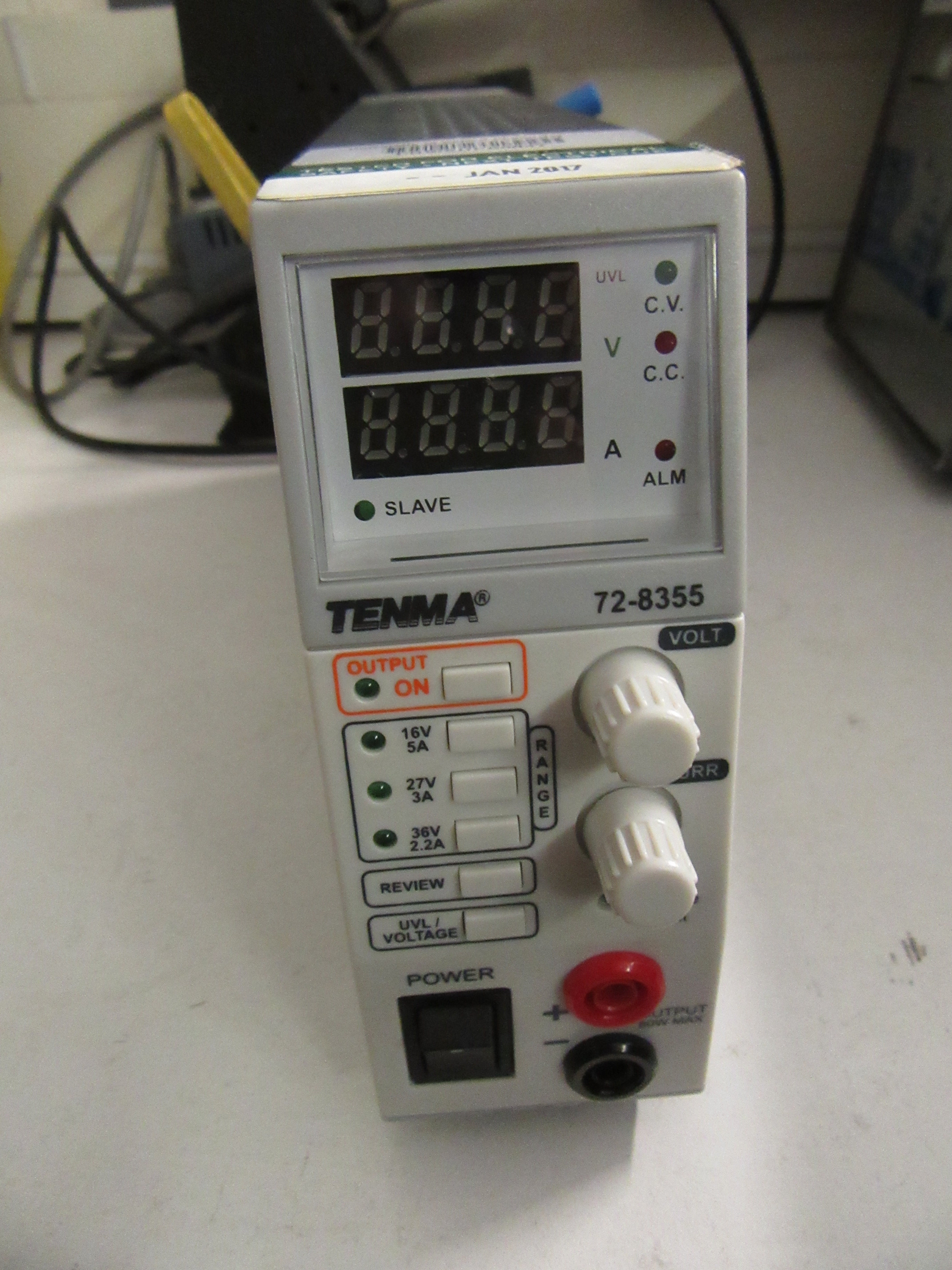  
Those are some of our power supplies available.
The left is a SWPS (Switched Mode Power Supply). The advantage of this style is that it is small for the power output, however, depending upon the modal and design of the output circuitry, it can produce a significant amount of noise (kHz-MHz) on the output that may vary depend upon the output load.
The other pair of units are linier units which only produces 50/60Hz of noise, if any. This is easy to filter out because it is of a fixed frequency independent of load, unlike the SWPS. Limier units generally get comparatively heavy once you get over 50VA.
The middle one is a commercial unit that has variable output voltage and current limit (0-35VDC, 0-10A), and a variable current limit. the right hand unit is built in-house (see the end of the construction page) and only produces fixed voltages as standard.
With power supplies the main issue with them in general, (more so with linier supplies) is that the more power required, the more expensive and/or bigger they get. They also get harder to find when you get past 500W due to a lack of demand. Part of this is due the fact that people generally use either AC for more power than 0.5kW or batteries witch are used for transportation motors such as for cars or scooters which are the main need for DC power at this rating.
top
|
We currently have a few amplifiers, however pictures have not yet been taken.
They range in functionality, however, we don't have many due to not many people wanting test/loan units and the speciality of the units that is required.
top
|
There are a few uncategorised items such as soldering irons which people may wish to borrow.
Soldering irons are one of the more dangerous items in the workshop that we can lend out. This is due to the fact that they hide the fact that the tip is hot. This can easily cause burns so care is paramount. We have a number of them that can be leant out ranging from small ones (the tip is still 3mm across, so not as small as some people may wish for) to more standard sizes. We do have one or two that are massive in comparison (~20mm tip), however, they don't typically get used due to almost being un-wieldable.
With activities like soldering, they release fumes, which are toxic. We have a small fume extractor (pictured) to suck the fumes away and then filter them. This works by a fan pulling the air (with fumes) through a filter, extracting the toxic aspect. If however you wish to do it in our workshop, we do allow short term loaning of a spare bench to carry out such procedures which has a fume extraction system designed to hook up to our irons, taking the fumes away at the source (and then through a filter).
Should you wish to do something that releases a lot of fumes, then it is recommended to either use a fume cupboard which is designed for the purpose, or if the job is too awkward the mechanical workshop has a large area that may fit the purpose, however they need to be asked before use.
Along with providing equipment, we can also produce technical drawings for circuits, so should you wish for a smart drawing of a circuit, we can produce one from a scrap of paper if wished for. The software that we use is tricky to use, so it is unlikely that you would grasp the ropes for how to use it in a sensible time period.
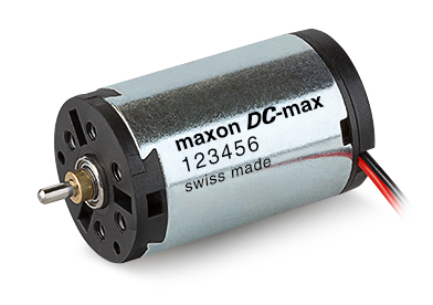
On occasion, people have wished to drive a motor. We have a small supply of motors and associated drivers. If you come by we can discuss witch may suit your purpose and may be able to offer a suitable test unit. Our stock primarily consists of DC brushed motors and AC mains motors. Because most of our motors are second hand, we cannot guaranty that they will be in the best condition or have the specification that is actually required.
top
|
| |
| |
| |