There are many type of component.
Resistors
The easiest to recognise and tell what they are, are resistors. Below are two images to help recognise the value of resistor that you are looking at.
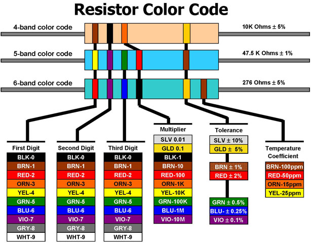
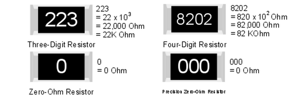
Once you know what the resistance of the resistor, you can then start dealing with the other aspects. Most standard circuits use 1/4W resistors as the standard through hole component. This is because they are typically cheaper than other wattages. For surface mount versions, the main variance (beside resistance) is in their physical size.
Some people may think why is there a zero ohm resistor? This is useful for allowing a connection to 'jump' over another connection in a circuit without the need for an additional layer to the board (potentially adding complexity). In some circuits such as when dealing with op-amps, there are 2 resistors that control the gain. Should the design of the circuit only require the unity gain to be used, this would call for 1 or 2 zero ohm resistors to be used. This would enable the user or manufacturer to easily change the value in the future when the requirements change. Sometimes, this is labelled up as a SOT component, or 'Select On Test' indication that the designer was unsure what the actual value needed was, or allowing for a table with various values to be used, depending upon the actual input/output, such as for power supplies having several output voltages available, and one board design/schematic.
Chips
The next style of items that can be easily recognised are chips (not the potato chips from McDonalds!!). This style of component is typically a black plastic (as pictured below) cuboid, however may be made of ceramic due to better heat dissipation (but more expensive). Surface mount chips are a similar colour, and instead of having the pins go straight down, have them come out horizontal at approximately the same level as the bottom of the package.
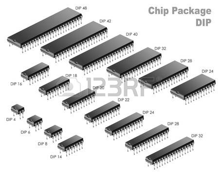
The standard DIP package has two rows of pins, 1 down each of the long sides. Because those have been around since before the majority of measurable items moved to mm, the pins are spaced at 25 thou (thousandths of an inch). Most chips have 6,8 or 14 pins (3,4,7 pairs of pins).
There is some form of marking that indicates which pin is pin1, either just to the left of either
the half moon in the end of the chip,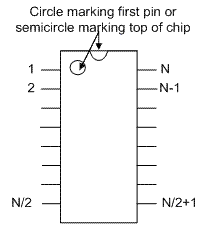
a small dimple by the pin,
painted end of the chip.
The chips with pins on all four sides have a different pin configuration, and are less common for most non-processor chips.
The typical chip has some writing on, with a number e.g. 74ls2022 indicating what type of chip it is. Some chips may have more information such as manufacturer. In some situations the writing needs to be caught in the correct lighting to be readable. This is due to more modern cost cutting measures, and use of lasers to write the information on. In some situations, the top may have been filed to stop people trying to copy the circuit. This is mildly irritating, as it also stops us from repairing the circuitry!!
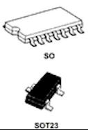
In more recent times, those packages have become smaller and flatter due to the manufacturing process. This has lead to the introduction of surface mounted chips, which take up less space. The issue with this type is that they cannot take the signal/power through the board, causing the issues with design of double sided boards to change. Were the issue was that the chip took up space on both sides of the board, it now only takes up one side, but is restricted to only having connections on one side of the board.
The image (above) shows two surface mount chips, one in a standard package similar to the standard DIP package (pin numbers are identical, and functionality can be identical, power dependant) and the lower one is a typical transistor or dual diode array in surface mount form.
Microprocessors
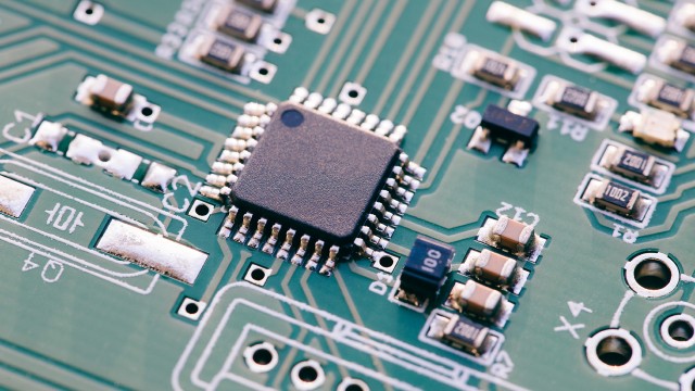 The standard microprocessor now uses a TQFP similar to the black square left. Some still use a DIP package such as the one used for the arduino uno (the ATmega328P) comes in a DIP package along side a TQFP
The TQFP range of chips area similar to the DIP package components. Those take up a bit more space in some dimensions on the board (more width to reduce length), and are typically square instead of rectangular. The pins get divided out between all 4 sides, and there typically are in excess of 64 pins (8 per side) such as the one pictured (above). Around the chip there is typically some other components such as capacitors (ceramic items below right of the microprocessor) and a transistor (above right) with 3 pins. One issue with the TQFP package is that they are less easy to replace in comparison to the DIP package if it goes bang.
All chips (and in particular the microprocessors) need to have some capacitors around the power supply pins. This is due to the fact that they can be asked to work at high frequencies, so need to have some buffer to allow the current to flow from the main power supply capacitors to the chip in question. There is less of a need for this when the either the chip is a few mm from the main capacitor, or the tracks are large, causing less inductance. This is one reason why more power hungry components are nearer the main capacitors. There is sometimes a second bank of electrolytic capacitors on a board at the opposite end to the main ones to try to reduce the strain on the circuit and the main capacitors.