In the past we have produced several complicated, interdisciplinary jobs. This may be asking for advice from the other disciplines on how they would make or adapt something in the future, to one section making a unit up and handing it to the other section for finishing off. Some jobs also are separate until the user gets hold of them and they add the finishing touches such as cleaning the unit before placing it into a chamber. Sed congue vestibulum facilisis. There have been some jobs were due to the amount of work that is needed from the other disciplines is minimal and achievable with our skills, we have carried out all of the work. This reduces the time pressures on them, allows us alter the design during the machining, and the job can be completed faster.
For some of our bigger projects, see those additional pages;
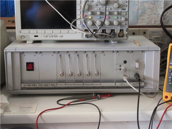
This one is a set of piezo drivers. It speaks to a computer via USB, whereby each of the 5 piezo drivers applies a separate voltage to a set of 5 piezo elements that are essentially glued together. This allows the user to move the end face of the piezo element parallel across a surface allowing the user to measure the friction, hence the interaction between the surface and the end of the piezo element. In this unit, there is one section that provides the power to the rest of the unit. It takes the mains coming in and outputs 5-12V to supply the digital circuit and the primary amplifiers, with a further 150V to supply the 6 output amplification units. There is some fancy circuitry to enable the circuit to register a short circuit and stop damage occurring.
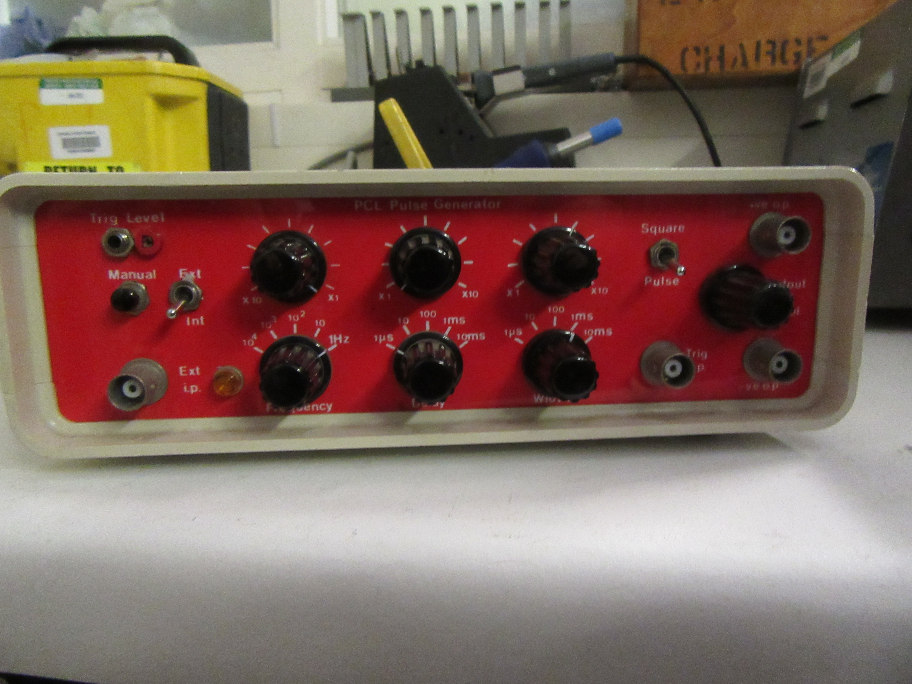
This is one of our older loan items, a pulse generator. We made several of those with different layouts and colours reflecting the builder. The unit quite simply, put out a pulse train at a set frequency/width. This frequency/width can be altered by the dials on the front, but the main drawback is that the values are not easy to repeat. They require a steady hand and an oscilloscope to be accurately set.
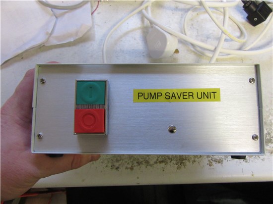
Teaching people to do things in the correct order can be tricky, so 1 group asked for a unit to stop the oil being sucked from their pump into the rest of the experiment due to the vacuum still being present when the power was turned of, so a value was installed between the pump and the rest of the experiment. When the red button is pressed, this unit will close the normally closed valve, and turn the motor off, so the experimenters don't have to adjust the valves.
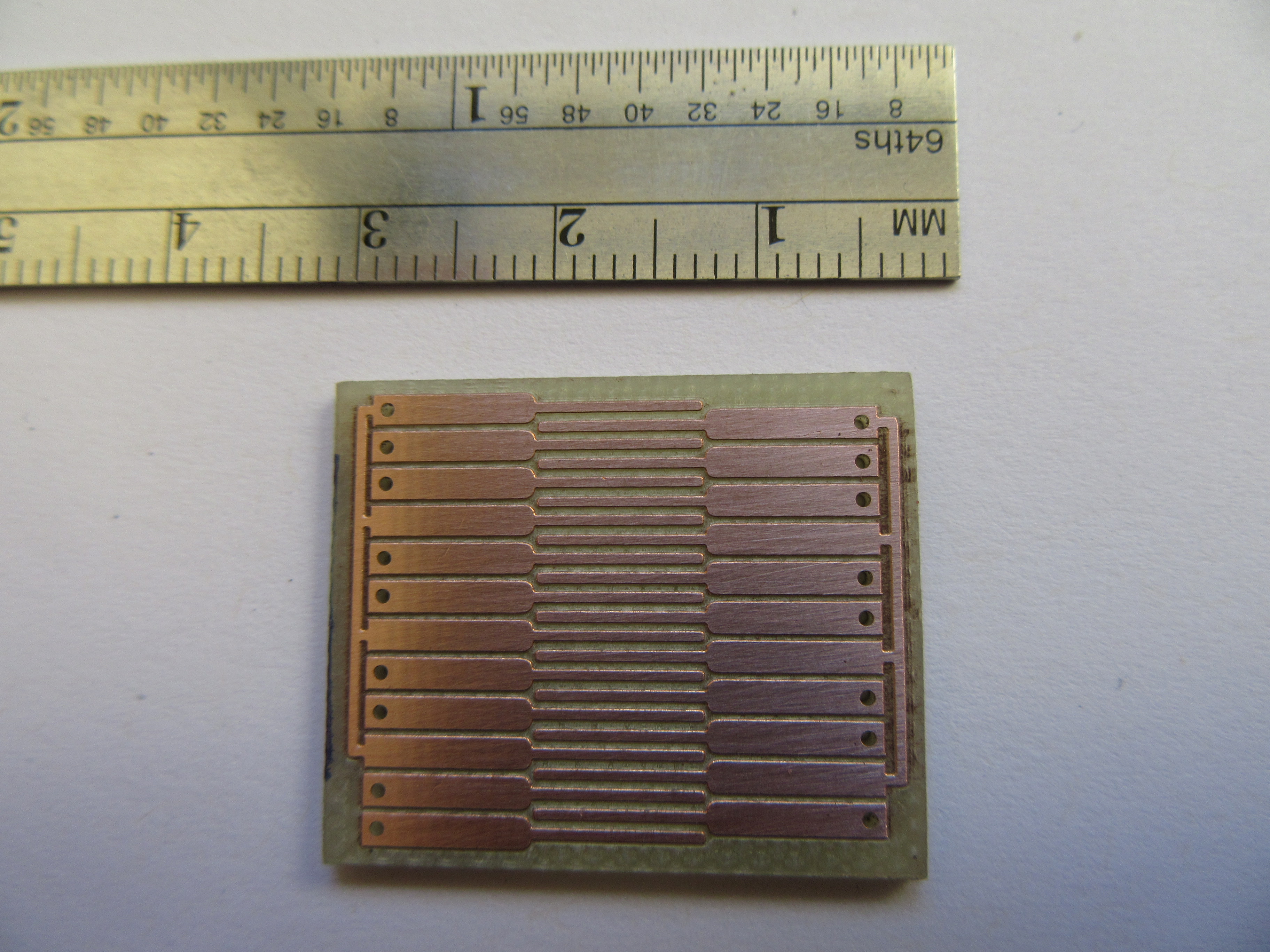
This piece of circuit board was used to redirect and slow down a beam of ions. Tim produced a box that connected to a digital I/O card on a computer, converting 3x16 bit parallel connections into 3 bipolar signals, which were scaled up/down by a potentiometer so that the user could alter how the ions hit the target after the device. The circuit board went through several iterations until we came to the final design (not pictured here). The final board that went into the chamber was produced on a PTFE board instead of the normal fibreglass due to the improved vacuum capabilities. The boards not in the chamber were made using our standard fibreglass board so that we could line up the board and the user say if it was OK, or if a change was needed. The reason that we chose PTFE boards was because they outgas less then the fibreglass i.e. they don't emit many gasses under vacuum. The benefit of this is that the user can take less time to get to a better pressure, so they can carry out more experimentation in a given time. It also means that around the critical area i.e. were the molecule beam was passing the circuit board and then hitting the target, there are less stray molecules to interact with, allowing for more accurate results. (Some experiments allow there to be some outgassing, but generally this is far enough away from the actual experimental zone, allowing for small amounts of fibreglass or other 'gassy' materials.)
The circuit proved irksome, the user and experiment wished that all of the channels to be equally matched in terms of voltage and time. The solution to this was to have the 3 pairs of channels (3 were the inverse of the other 3) go into an modulation circuit along with a voltage from a dial on the front panel, and then amplified by +2 or -2, each channel being tuned around this value of 2 to get them to match. This was then sent down 6 separate wires to a unit mounted right by the chamber, where it was amplified from around 40V up to around 140V, and applied to the PCB above. The final amplification was done right by the chamber so that any distortion was kept to a minimum,
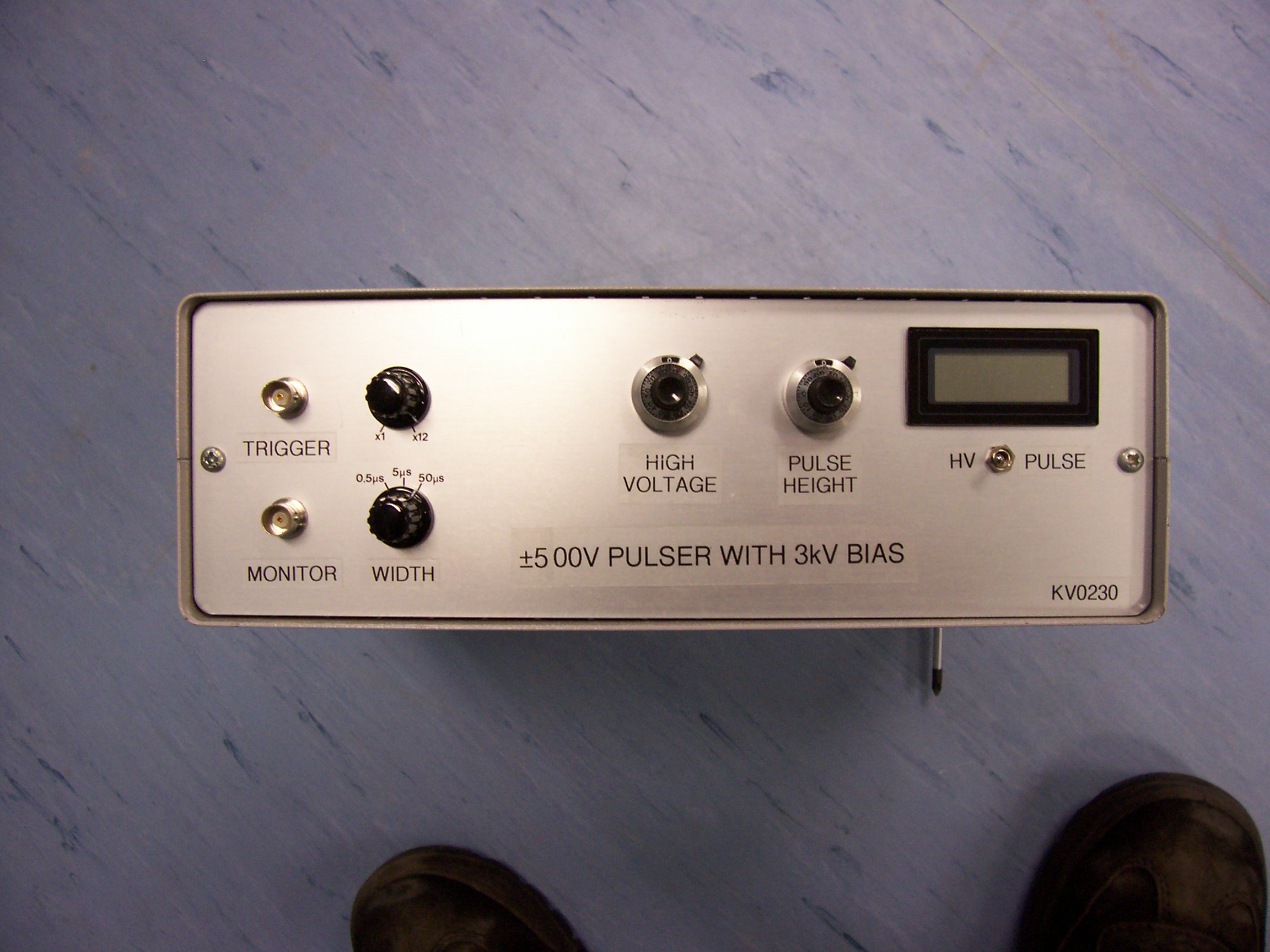 This unit sets a very simple pulse on top of a baseline voltage of 3kV. This caused an issue for the circuit that creates the pulse because it needs to be isolated from the case and ground, which are the normal reference points. This unit has no theoretical limit to the pulse width, however, it would typically be in the region of a few micro seconds up to seconds.
This unit applies both the 3kV baseline and the pulse signal from the same box.
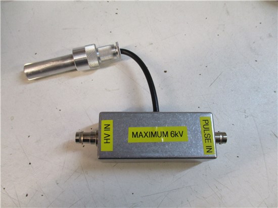 With some groups they wish to apply a pulse to a voltage coming from a separate power supply. This box (right) capacitivily couples the signal onto the plate, so the low voltage signal (pulse in) needs to be fast otherwise it will deform across the capacitor. The limit for the baseline of this box is dependant upon the capacitor used. As the maximum voltage goes up, the maximum capacitance decreases along with the width of the pulse decreases, due to the time constant of the circuit. This is a passive version of the previous unit.
 This is one of our multi-out power supplies. We have made a lot of them to power several (typically <=4 per power supply) low power units that can be built smaller and cheaper. Some units that use one of these units for power need to be close to the chamber to reduce the capacitance on the high voltage signal. The low voltage signal can then be transmitted down 50ohm cable with minimal/no distortion.
The standard unit that is made has +12V, +5V, -5V and -12V available on all 4 connections. some have been modified to give +15V and -15V either instead of (in the same profile) or as well as (typically in a bigger box), the standard voltages. Those are rare due to not many users wanting the extra few volts. One issue about those units, is that they cannot power hungry units. They have a limit of ~250mA for the 12V rails, and ~500mA for the 5V rails.
Depending upon the creator of the unit, the connectors may by installed in different orientations, however, the user shouldn't be able to plug the unit being powered in the wrong orientation. If the plug is not going in smoothly, ensure that there is no plug already in the socket, and that the orientation is correct. If problems persist, please come and ask one of us for assistance.
 Because there were a number of people that started making those units, they naturally chose 2 standards for wiring the units up. As expected, this caused confusion (and the odd bang/puff of white smoke). At the moment, we have spoken several times about converting half of the lab onto the other standard, therefore reducing the number of standards to a more convenient 1. This has been received by inaudible mutters; and is pushed 'under the carpet' for another few months/years due the enormity of the project and the chance that a unit will be missed on a critical job. For new, it is recommended that you don't trade between groups unless we have said that you are on the same wiring standard.
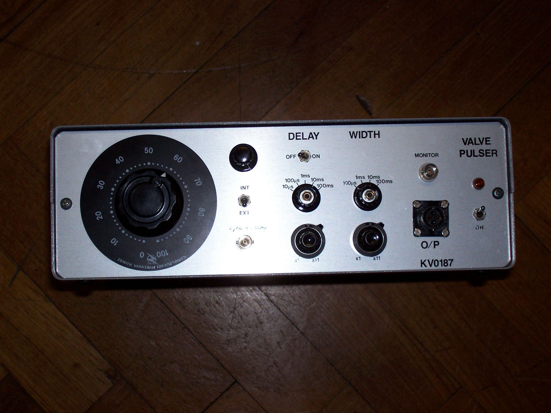
Several groups use pulsed jets of various gasses. There are several ways to achieve this;
Firstly you can have a motor spinning a cut disc/fan blade. This transforms a jet of atoms/molecules into a pulsed string. The main benefit of this style is that the pulse edge can be guarantied to be fast. The frequency and pulse width of this style are both directly linked to the speed of the motor. The faster the speed of the motor, the faster the frequency and the shorter the pulse of gas. One issue with this is that there is a time were the motor is spinning up/slowing down were the pulse string is not at a fixed rate. Another issue is that you cannot always tell when the pulses will start/stop without a sensor in the chamber. Should this style have a failure then due to the kinetic energy involved in a fast spinning blade, significant damage can occur to the chamber and contents. In this case, a suitable shield is strongly advised. This brings the size up to a more comparable size with the valves. With more modern motors they can be controlled by controllers run of either single phase mains or a DC voltage source (power dependant). With this style, they generally require some way to turn the gas flow of when you are not running any experiments, such as when the system is pumping down.
What most experiments needing pulsed jets in the department use, is a valve. This takes a gas line and emits a pulse output. This is operated by a box (see image) that opens the valve fast and then holds it open till the box turns of. This produces a pulse string of which the width and frequency can be controlled independently of each other, and modified after the whole setup has been taken down to a vacuum. Should this type of valve fail, there is very little damage to other parts that can occur. This is due to the fact that the ball bearing is held in place by the pressure difference across it, and the rest of the unit doesn't have much, if any mechanical movement. The most common fatal/near fatal failures are either a fitting is badly screwed onto the input, or a wire breaks of, both of which can be rectified if the user realises early enough and does something about it. Should this user wish to stop the pulsing of gas, such as if they are not running any experiment or they are pumping down, they only need to turn the unit off or unplug the valve. We have designed a plug on box that will simulate the valve, and allow there to be a monitoring point to a scope. This enables the operator to observe what the control box is emitting, and if/where there is a fault.
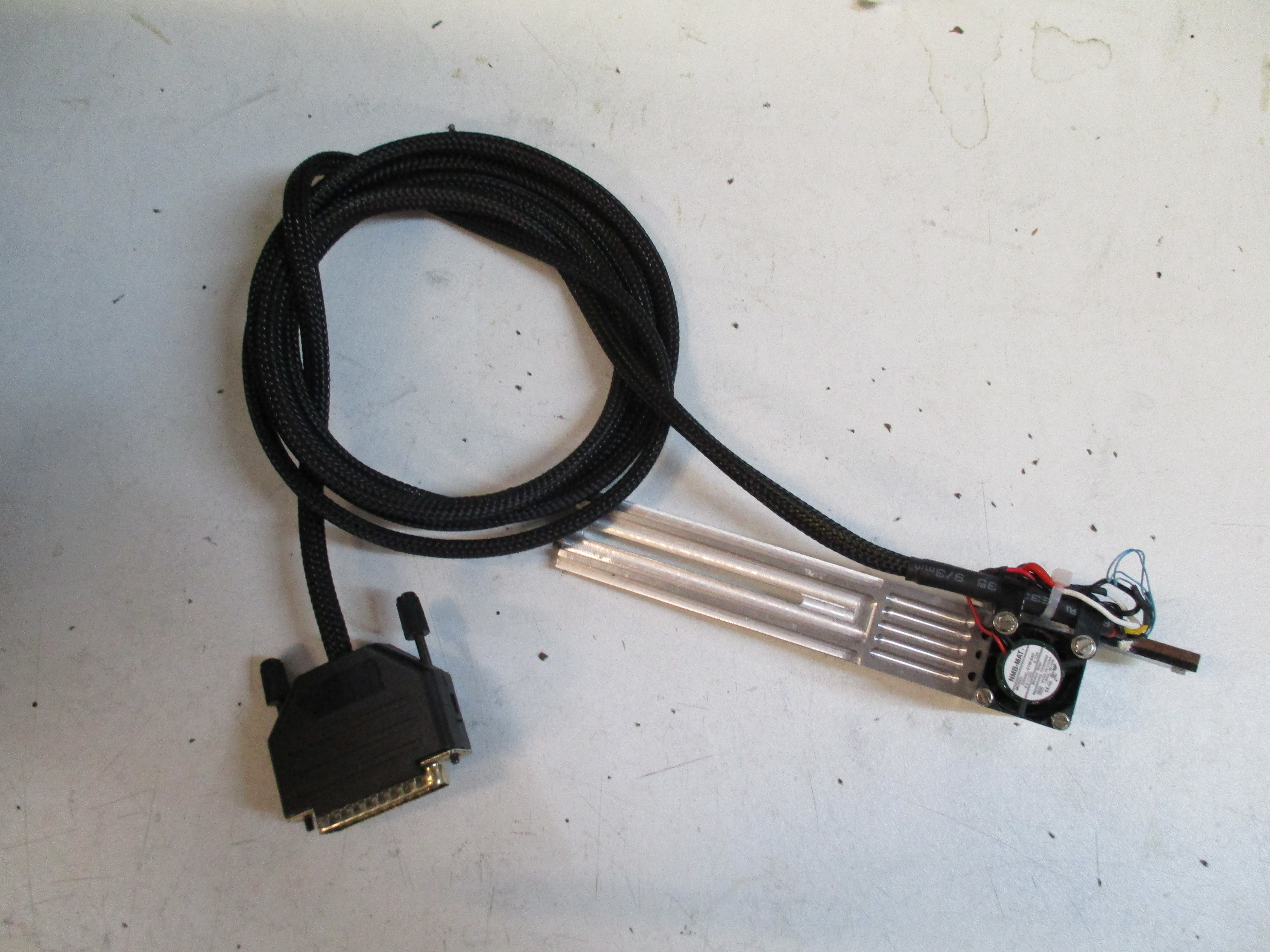
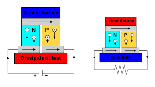 One group whished to print tissues into a cooled solution. This was achieved by means of a peltier. A peltier works either by passing current through the substrate; or by having a hot and a cold side, and current flows out of the cable.
What we did was have a bar of aluminium made with lots of holes drilled horizontally through it. Air was blown through those holes, providing some cooling. Onto this block was screwed a copper block, with the peltier unit sandwiched between the pair. The screws were to ensure that the four surfaces stayed in contact with each other, and, allow the user to maintain the location of the cooled item, whilst the material used for the screws (nylon) was because it is a poor conductor of heat. copper was used for the controlled surface because it has a high conductivity of heat, lending itself to easier control. The aluminium has a lower conductivity of heat compared to the copper, however it was decided that to reduce cost aluminium was suitable.
A separate unit was made to power the fan, measure the temperature of the copper block (through a thermistor) and control the current flowing through the peltier, hence, control the temperature. This box has a plug to connect to the pelter assembly so that they could either use the temperature control aspect or leave it disconnected, depending upon what they were experimenting with.
One group in the lab uses Faraday cages. This involves having a large box made out of metal panels. The panels stop the electromagnetic radiation from entering the unit and affecting the experimentation.
Depending upon what the experiment is, the user may also require the unit to heat. This is achieved by heating the inner walls of the double skinned chamber with some heat pads (typically around 200mm by 200mm and mains powered) and having the remaining space filed with insulation. The mains frequency is stopped by the inner skin of metal. Within the chamber there can be a fan that blows the air around to attempt to maintain a constant temperature on a temperature sensor located close to the actual experiment. Essentially, the sensor controls the PWM of a solid state relay (SSR) or a mechanical relay (less often for this job now due to a shorter MTBF). This is located between the heaters and the mains, allowing the temperature to be reasonably constant around the experiment. All of the control circuitry including a PID for the temperature is contained in a separate box that can be stored on top or under the Faraday box (assuming that the cage has legs). This allows the user to take the control box away, and potentially use it on a different setup with the same settings. On some cages, there is a switch for 'low' and 'high' power which switches the heating panels between series and parallel connections, altering the effective power of the heating panals.
top