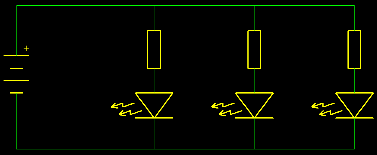
This circuit is an example circuit for how to wire some LED's up.
Each of the 3 LED's pictured can have a different voltage required across them. Red LED's would typically have 2.2V, compared to 4V required by some blue LED's, however, the voltage will change depending upon the modal of the LED.
Because the standard 5mm indicator LED will require between 5mA and 20mA depending upon required brightness, the user can then change the resistor to alter how bright the LED is.
The advantages of using this setup as opposed to having all the LED's in series is that you can set the brightness of each LED, and can keep the voltage at a lower value, however, the current will be dependant upon the number of LED's.

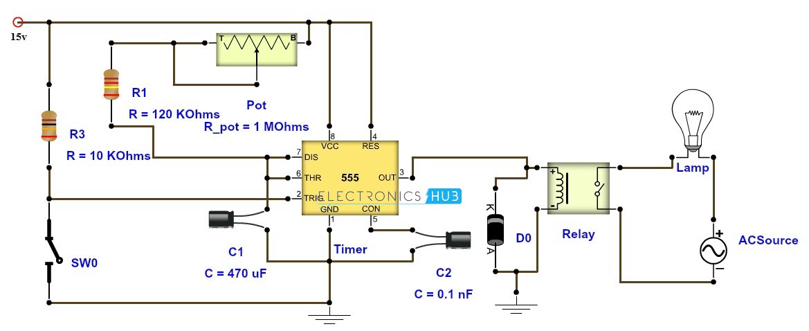
This circuit has 3 aspects.
The first consists of a basic trigger circuit consisting of a resistor(R3) and a switch(SW0). The switch provides a trigger to signify when to turn on the output lamp. The resistor is placed here to ensure that the line is pulled high when the switch is not being pressed. This stops the circuit from being falsely triggered.
The next part of the circuit contains a 555 timing chip. This chip can be setup in several ways (see datasheet). When used in this way, it will only trigger once, and only when it sees press of the switch. The Pot at the top of the circuit can be adjusted once the circuit is made to alter how long the output lamp is turned on. The preset values of R1 and C1 will set the range of this pot, and can be decided on from a read of the datasheet.
The final part (from the output of the timer chip) consists of an electro-mechanical switch (commonly called a relay), a diode, the lamp and supply for the lamp. The relay has a diode across it because when the circuit turns of there will be a reverse voltage applied to the timing chip. This can cause damage, so the diode will take away the problem, and increase the lifespan of all components. The lamp and the power supply on the output of the relay can be switched out for other component sets, and the advantage of a relay (as opposed to some components such as a transistor) is that it can accept either a DC voltage or or AC voltage and can generally switch 50V+ such as mains voltages, allowing for the timed on/off of powering of units.