We have had numerous people come down and request either LED's or the systems to control them. The use of them in the experiment(s) varies, and none are exactly the same. The two main categories are surface mount (SMD) or Panel mounted.
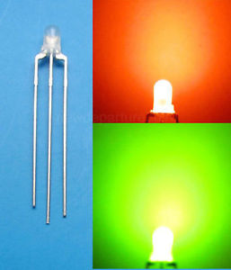 Some LED's have multiple emitters in the same package. On 2 pin packages those can be the either the same colour to increase the light output, or in some cases, they can be connected up to the same pins so if the current flows in one direction, it lights up one colour, and in the other direction, it will light up as a different colour. This can be used in charging circuits so that the LED is red for charging and green for charged. Some have 3 pins and 2 emitters; those can have the current flowing through one, the other, or both allowing for a potential of 3 colours. e.g. green and red make yellow or any shade thereof. This style of 3 pin multicolour packages are more common with the panel mounted LED's than the surface mount units.
With both styles of LED, they come on various levels of danger. The majority of the panel mounted LED's from the visible spectrum don't cause significant damage due to the human aversion reaction. The UV LED's need some sort of protection. Most of the surface mount ones can produce enough light to temporarily blind someone, however they typically get used either at lower powers or in a situation where the user cannot look into the LED, such as from behind a tinted screen. In a situation where the user may get blinded or otherwise injured such as the wavelength of the LED being in the UV range, then a container can be manufactured. One box that has been previously made is about 500mm cubed. This has an removable interlocked lid on and a flap on the side for the wires, so the user can set up the experiment within the unit and put the lid on before turning the unit on, alleviating the issue of directly viewing the light source.
If the setup uses a dangerous wavelength it should have an interlock attached to the container to stop people from looking in whilst the danger is present, such as the unit below. In rare cases, this setup may be connected up to the room interlock in the lab, but this is rare.
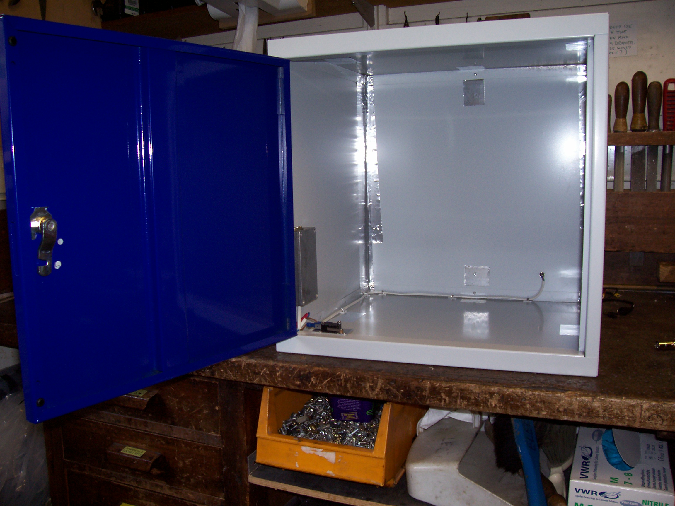
 This is an example of a light chamber that we have made up for a UV light source. It is quite simply, a locker, of which all of the holes have been plugged up/covered over, allowing the user to operate around the box without exposure. When the door opens, there is a small switch that turns the light source off, allowing the user to access the inside of the unit when the source is off, hence, reducing any hazards. The controller in the box (in a small die cast box by the hinge) is powered by a power socket located (in this situation) in the back panel. Because the controller is small and located out of the way, it maximises the operating space for the user, experiment and any monitoring equipment. One of the advantages of this being a locker is that if the user wishes to do an experiment for a period of time then the key can be removed after locking. The main issue with this through, is it is easier to loose the key. Because the control box is screwed on the side it can have holes in the wa
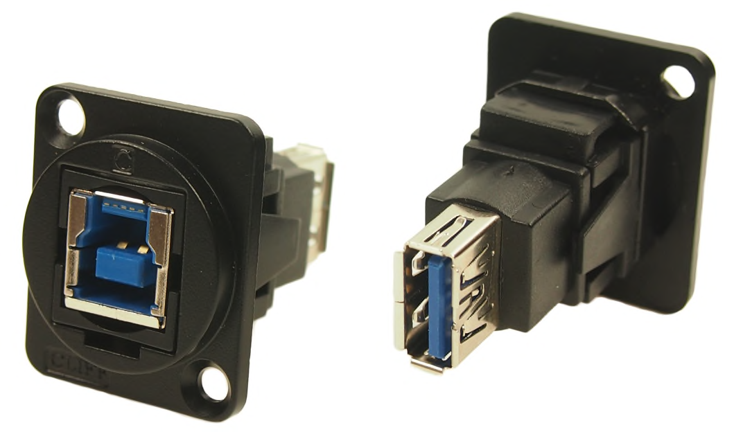 ll allowing for items such as input controls for adjustments during the experiment to be fed straight into the control box. Other items such as a USB socket for a camera or a mains socket (box size dependant) can be fitted to maintain a light-leak-proof environment.
top
Panel mounted LED's
This style is generally used when the LED is to be mounted onto a front panel of a unit. This is due to the rigidness of the LED's frame, ease of attaching wires to the leads and all that is needed is a hole, which we can then put a fixture into contain the LED. The typical LED comes with 2 legs to attach wires to. Some LED's have 3 or more legs so that the user can have multiple colours in the same package. We only keep 2 or 3 pin LED's. With 3 pin LED's 3 colours can be viewed (colour A, colour B or the two mixed). Because this style has a sensible viewing angle and brightness at their maximum voltage/current rating, it is easy to connect up to signal lines as indicators. This most common style that people use is typically 5mm diameter by around 8mm long.

The first image is of a 5mm LED, the second containing most of the standard shapes of panel LED, of which the design has been around for years. They are typically cylindrical, however some are cuboidal in shape. Typically this style wont blind the user like their surface mount relatives (below). They also are very easy to solder to. If you come down, then we have a reasonable stock of 5mm in red, yellow, green, and blue with a few white. We also have a limited selection of 2 and 3 pin bicolour LED's.
Typically the LED's that we have a stock of require between 2 and 4 volts (the datasheet should be consulted for the actual value), so to be able to safely use them without them blowing up it is recommended to use a resistor in series to limit the current. This also allows the user to operate at a higher voltage across the system, allowing more control of the LED's brightness. Most systems that are likely to need an LED of this style work with 5V, so the resistor would need to be a few hundred ohms and dependant upon the voltage rating of the LED. The maximum current rating for this style is typically 20mA.
This style of LED was the first style that was commercially available. The size of the LED was chosen because it was large enough to be worked with, yet small enough to be handled.
top
Surface mount (SMD) LED's
This type of LED is typically mounted onto a piece of PCB. The PCB provides support for the connection pads, and a way for heat dissipation (if needed). The smallest are 1-2mm tall and 2mm square.
a.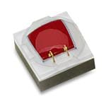 b.
b.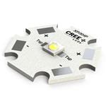 c.
c.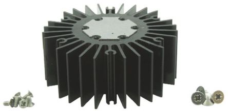
(all images not to scale)
With the LED's that we get, they arrive in 2 setups; some are bare LED's (e.g. picture a) and some are already attached to a circuit board (see picture b above). If they come without a heatsink (the white part of picture b) then we attach them to a suitable board. Typically the board we make and the commercially soldered units are attached to a heat-sink such as the one in pic c above. Those come in different sixes dependant upon the heat dissipation.
Because science always ask for something different, we can buy 90% of the LED's as chips as pictured above (pic a), and not attached to the board. The issue with this is because they can be small (a few mm across), it does take a skilled hand to attach them to a circuit board, so it is advisable that we do this step. One key issue with attaching them in the is manner, is the heat sinking when the LED is used above ~10% power. The easiest way, is having a heat-sink on the other side of the circuit board. This can either be a block of metal with a heat pipe to elsewhere (which then has another cooling method e.g. fins), forced air tubes or a water cooling system. Most of the time forced air or a heat-sink 'on site' such as picture c above is the best method.
The easiest and most common way to use those chips is to have them mounted up like pic b above, and then screwed to a heat-sink such as pic c. Wires can then be taken to the back of the heat-sink, where they can be attached to the heat-sink through a supporting clip and some stronger wires to a control circuit. This allows the user to apply stress to the wire leading between the LED and the power source without damage to the LED. The heat-sink pictured has 4 screw holes in the back which can be used to mount it within the users setup. 1 is typically used as a strain relief for the wire, and the whole device can be mounted on only 1 screw hole if needed.
This style can take anything between 3VDC and 12VDC depending upon the led being used and up to 1A of current (the datasheet should be consulted for the actual values).
What we have done in the past is create a small box that the LED cable can plug into so that the light output level can be readily controlled. We keep some controllers in-stock so that they can be soldered into a board reasonably easily, and used in the lab within a few hours. The controllers that we use can have a PWM input and an analogue input, so there is room for multi-functionality within the units. If the user wishes to only use a section of the brightness level, we can add suitable resistors into the analogue input control, thereby limiting the brightness to roughly the required amount.
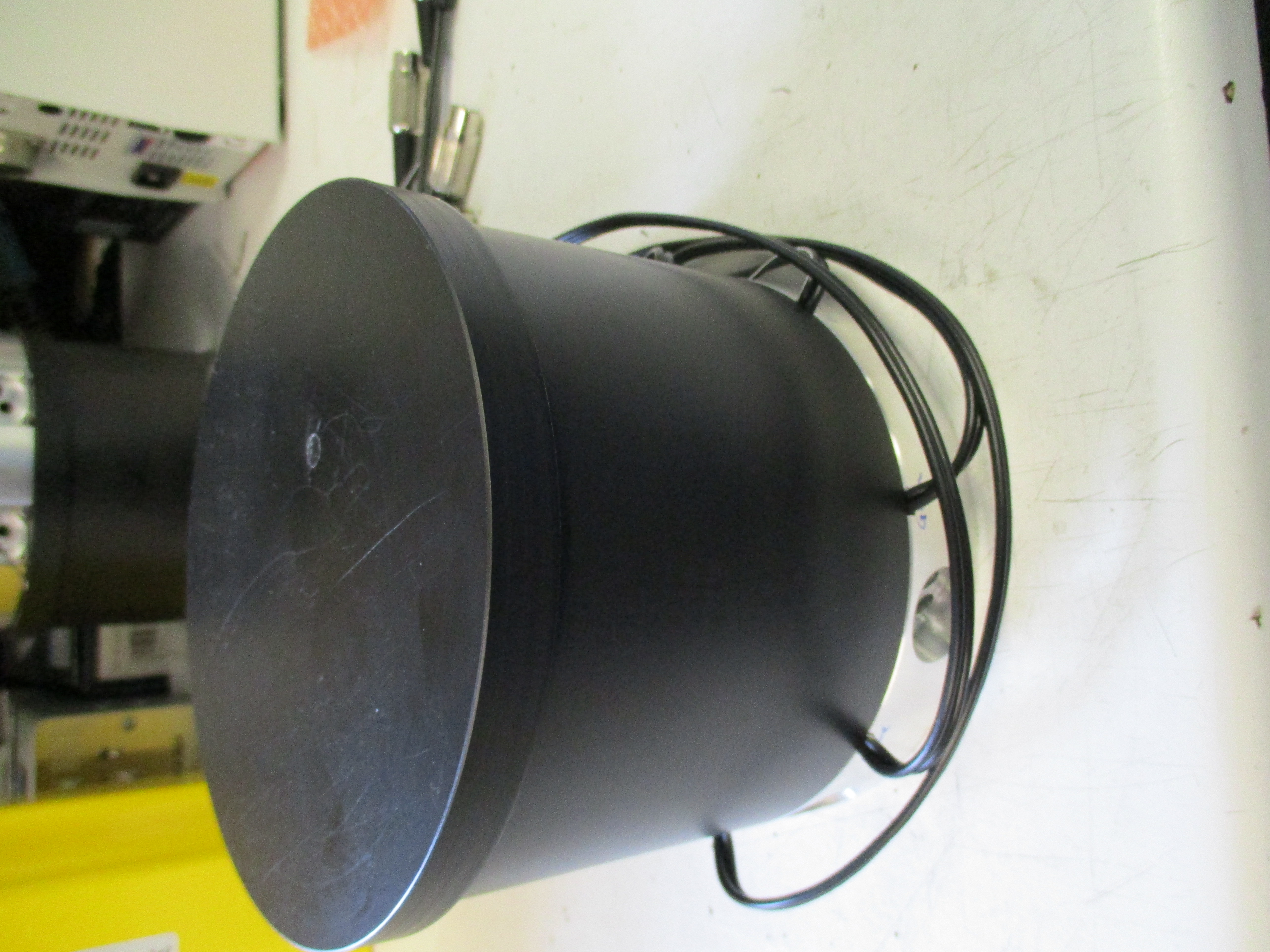


Those three images (above) were designed for housing 10 of the SMD LED's in 2 wavelengths. The aluminium plate at the bottom has a pair of fans to blow air through it. Even through the fans are blowing through, the plate does heat up and it was recommended that either they were not all on at the same time, or they were set to a low brightness. The experimentation compound/liquid is contained within vials that slot into 10 holes in the top face. The 11th hole (with a yellow mark below) is used to interlock the lid. This turns the LED's to an ultra low setting, which is considered safe, however, it is best in this setup to turn the setup of completely before lifting the lid. This design can be replicated for other frequencies, or for other styles of experiment.
top