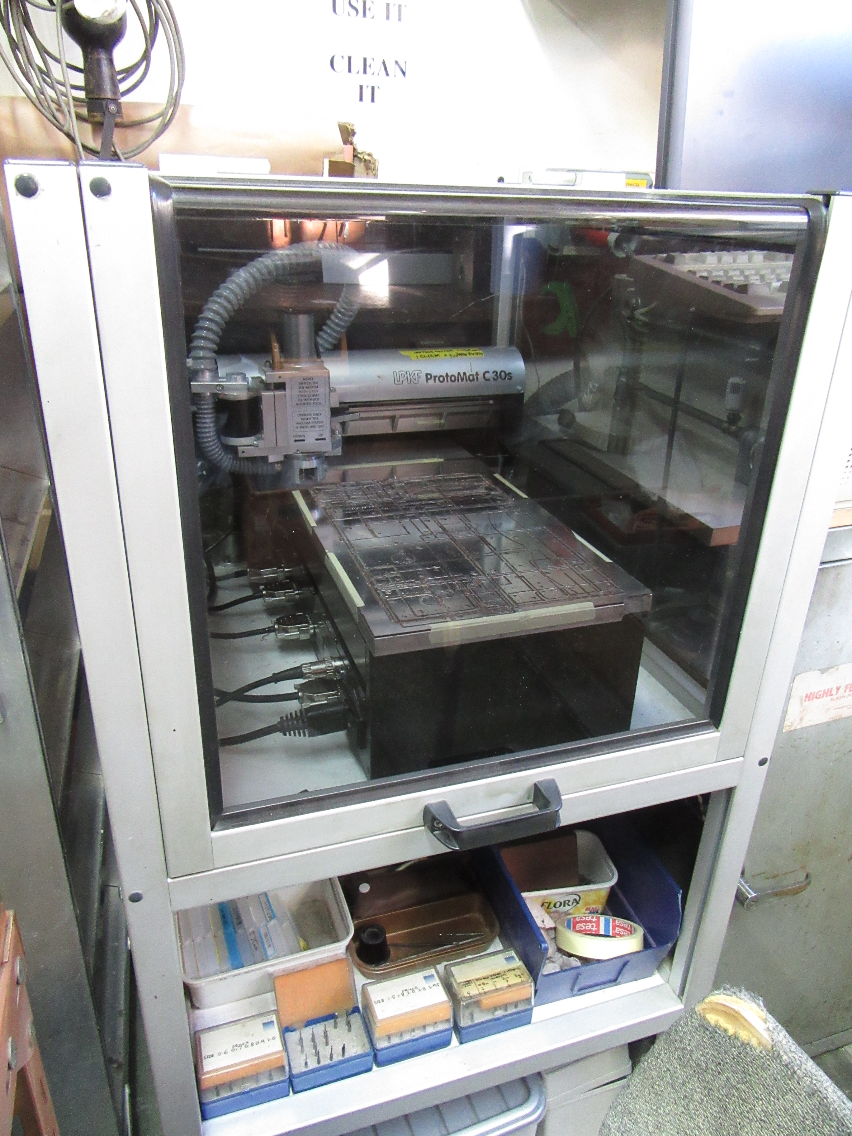
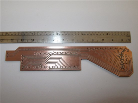
 We have a wide expanse of knowledge in the building of equipment. Within that knowledge is the ability to control a PCB router that can produce boards that accept most sizes of components and packages. We do have contacts in other departments that can sort out other types of component that we don't use regally such as BGA (ball grid array) chips. We don't regularly use this style primarily because of the difficulty caused by soldering the pins in the middle of the chip.
With our PCB machine, we can achieve various shapes and sizes, however it cannot necessarily achieve small angles or small slots! We can advise on what it can achieve when you come with your job request.
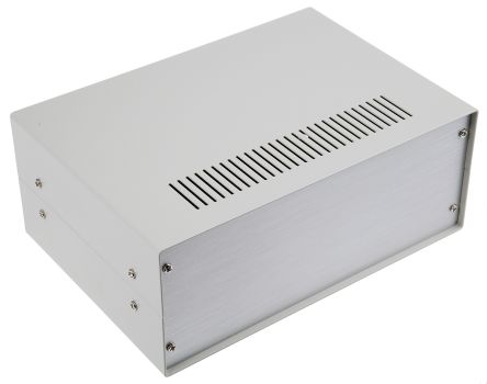
 Most of the time the boards that we produce get tucked away inside standard boxes (a range of different dimensions) so that you, the user has an easy to use interface. This has allowed the workspaces of various academic staff to have less clutter in their workspaces.
Sometimes we get boards made up out of house, however, those are generally for mass produced items such as current drivers for lasers. The reason for this, is that although our router is good for one of units it can get a bit tedious making a large number of items. Also, if one person is holding up the machine for a few days then the rest of the team cannot use the machine, potentially holding up their jobs, so we generally like to avoid this situation. There is a contact that we have in another building who can produce larger circuit boards than us, however, because he works for another department, we don't like to bother him unless we need to!
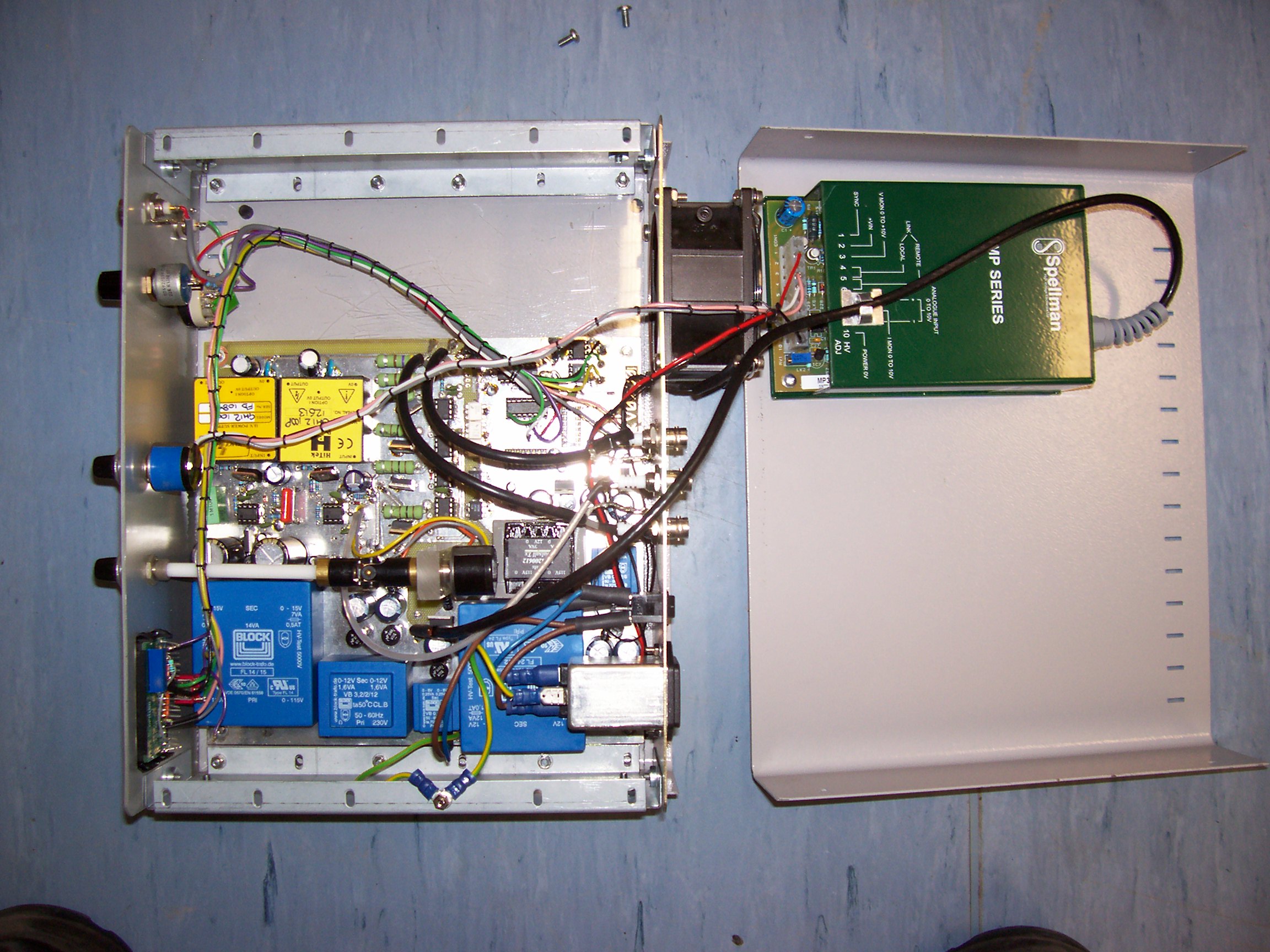
This unit utilises both an in-house built board, and an externally built HV power supply. The board in the left half (in-house built) contains a power supply taking the 230VAC and outputting 12VDC for the HV supply, along with the control voltage for the high voltage. It also contains some controls that affect the output, such as pulsing the output or placing a pulse onto a DC voltage. The external board (within a case for HV saftey) from Spellman contains a circuit board with controls to alter the output voltage dependant upon an input signal (primarily a DC voltage level). This signal can be a potentiometer on the front of the unit it is going into, a pot on the HV unit itself (rarely used) or a 0-10V signal from an external circuit. The unit than scales this control to the full range of the supply, and puts out both the HV output (potentially 0-1kV up to 0-15kV, dependant upon the module version), along side a 0-10V signal for monitoring purposes, such as a display.
Past projects that we have made include controllers for multiple lasers so the user can control them individually from the other end of a USB cable. This involved a 2 stage process, one that takes the USB signal and converts it into individual signals for each of the laser drivers, and a separate laser driver for each laser. Each laser controller would typically get 3 signals; one output on/off (from the user/pc), one output on/off for the interlock (typically from the box's or room's interlock system, dependant upon the class) and a third analogue signal for the amount of current through the laser (also from the user/pc).
Other large projects include production of large Helmholtz coils, whereby our normal coil winding technique was used, but used on a coil former several times the normal size we have made.
For a few groups we have had boxes made up by the workshop and aspects supplemented by us adding some electronics. The boxes are designed to stop any unwanted electromagnetic radiation from penetrating the experimentation. Depending upon the end job it can have insulation and heating pads installed during production, and/or a separate compartment with electronics (shielded from the main chamber) that will interface with aspects of the main chamber. When the units are heated, the heating pads are controlled through a Solid State Relay (SSR) in a separate box. This separate box has a temperature controller to allow the user to control the temperature of a probe right next to the experiment. This can be moved around on a length of wire within the chamber, allowing the user to adjust which part of the chamber is controlled.
We have found that we can produce BNC cables of a higher standard than can be bought from suppliers. This is due to the fact that the process used to attach the shield to the plugs at the end is done to an inferior standard. We can also make the lead to the specification that you require. This involves an appropriate length and different connectors no the ends if needed.
When you come down requesting new leads, we request what connectors are needed (see below), and how long you require them. Some connectors are not compatible, due to cable size.
BNC, SMA, SMB, SMC(not common) and the small Lemo are (small) cable compatible.
BNC, MHV, SHV, Kings and the Large Lemos are compatible with the large cable we have.
The BNC, SMA, SMB, SMC and small Lemo connectors are not suitable for voltages above 250V-500V. We do not recommend using those connectors on the same lead as the high voltage connectors because mistakes such as connecting a 10kV power supply to an expensive oscilloscope will happen. If this type of connector


Those images contains the standard connectors that we connect to.
The Lemo pictured on the panel (left image) is a low voltage version, however, there is a high voltage version (right) that can withstand 20kVDC. For pulsed voltages around 10kVDC, it has been found that the high voltage lemo is the only one that can produce the signal without additional funny waveforms on the output. This was found out due a jumping image on a rig.
The letters for some of the connectors are referencing some aspect of either their history, or purpose. Below are a number of them;
BNC - Bayonet Neill–Concelman, after 2 of the founders Neill and Concelman
MHV - Miniature High Voltage
SHV - Safe High Voltage
SMA - SubMiniature version A
SMB - SubMiniature version B
SMC - SubMiniature version C
LEMO - after the founder of the company that makes them, Léon Mouttet
King connector - named after the company we get them from! The author is unsure if this is their proper name!
 One project that has had repeated orders in recent years involves Arduinos. This enables the user to be able to program/reprogram what the Arduino puts out allowing for easy adaptation/modification of the signals that the unit, and by extension, the equipment receives. This enables the user to be able to use a standard code (as far as the Arduino goes), and have a designer shield. Because the various Arduino units all have a standard size for each modal, we can generate a box or panel for the Arduino to reside in or on (if appropriate), with the USB connector and power connector (if present) available on the outside or edge.
Because most of the Arduino's have a pin for an external voltage to be plumbed into the circuit through the shield, we can hide a power supply with an Arduino inside a box so that the unit can fully function away from a computer or laptop. The Arduino is useful when the operator may wish to change the code on a regular basis. This is because the software can be easy to learn, and is useable on various platforms, basically, anything that has Windows, Linux or Apple software and a USB type A socket.
The Arduino 'system' is not used regularly in systems we produce because we generally use microcontrollers that once they are working, the program doesn't get changed often. If we need to reprogram the microcontroller, then in general need to do other modifications as well. Microcontrollers and the associated circuitry are typically smaller than an equivalent Arduino because there would be multiple chips carrying out the same function. Our boards are likely to use voltage regulators with a greater accuracy or current rating. Most of the systems that we have that communicate with through USB have controllers or drivers in lab-view or can be controlled thorough other software e.g. Microsoft Excel with suitable knowledge.
We have also had dealings with Labjacks (The type that plug into a PC, not for lifting experiments up!). Those are similar to Arduinos, but have better accuracy on the outputs, are all ready built into a case, and have decent screw connectors for the input/outputs. Those can speak directly to Labview and Microsoft excel (with suitable code). thee are premade tics which screw into the Labjack allowing the functionality to be changed. The downside (in relation to the Arduino) is that they cannot be operated away from the USB socket of the PC/laptop.
Similar o the Arduino is the Raspberry Pi. We have not had much to do with them, however we can and have connected some jobs up to them. The advantage of them is if the user wishes to run several operations at the same time, due to the multithreading ability and they can be connected to the ethernet (after authorization by IT). The code for the 2 units is different, so if the project is known to need the multithreading, then it should be used from the start. We have had very little experience at programming of the Pi but have contacts who may be willing to advise.
Some groups in the lab use lasers, so it can be arranged that your lab gets the safety features installed, however, as well as features such as door interlocks being installed, each person working in the lab needs suitable training. We can point you in the correct direction as too what is allowable as far as working in this area.
Some groups may allow you to 'borrow' their laser (or system) and probably a user for a short period of time, however, should you find that you/your group is always using the same setup or laser system then it would be advisable to get your room modified to accept lasers or request an official sharing of said laser system. If you want further advice on this subject, come and visit us.
For more info see the page on laser interlock systems.
We have had several groups request LED sources for various wavelengths of light.
The main issues with LED's are;
- If using SMD LED's the power wasted in the form of heat can be high (for the size) so ample heat-sinking can be vital,
- Some LED's either emit light in the various UV bands,
- SMD LED's can be so bright the may cause blindness, so some protection may be needed or control of the brightness,
Some of the wavelengths are reasonably cheap, however, when you start going away form the common light frequencies, it does become more costly. Should the LED be too bright or contain dangerous wavelengths, containers can be produced and/or procedures/systems similar to lasers can be put into practice. The boxes can also be used of you don't wish for the room lights to affect the experiment.
For more info see the page on LED's.


One item that we produce are multi-output PSU's were we can plug several small power units into for a low form factor concept. They are aimed at where there are several items, all low power, and would otherwise use up a mains plug each. This get round the problem, allowing one mains plug to be used, instead of 4 (in most modals of the unit). If the lab has several of those power supplies, the pluggable units can be swapped round easily between experiments. This also allows for a reduced stress on the overall mains system due to a reduced number power supplies.
Those units provide a low noise +12Vdc, -12Vdc, +5Vdc and -5Vdc on each of the 4 sockets. There are two standards that the 5Vdc and 12Vdc on the sockets are wired to; so if the unit has come form another group, check with us that the unit can cope with your groups standard.
Some of those PSU's also have a +15Vdc and -15Vdc pin, however, due to not many needing the 15Vdc, it is not installed as standard. The 15VDC units have a 7 pin socked set on them. The two extra pins are at the bottom, and the 5Vdc/12Vdc plugs fit into the socket as-well. Depending upon the wiring up within the power supply, it may have one or other of those voltages missing, however, it should say on the front if one (or both) is missing. Just like the 5V and 12V rails, the 15V rail is not the same on the standards so even if the unit only uses the 15V rails, care must be taken.
There is a half-baked plan to sort the dual-standard issue out; however it hasn't yet been put into action.
This (below) is one unit that plugs into one of the power supplies. As can be seen, there is not much within the unit so it is not worthwhile putting a power supply in seeing as the supply can be shared.

top