In the electronics workshop we have access to a range of tools, varying from an aging circuit board mill to more modern computers. We have a soldering iron each, and depending upon the operator, we can solder small surface mount chips, or larger DIP packages. We are always up for the challenge!!
People have come to us and asked for assistance in high voltages. For most people, this would mean 30V, however for us high voltage fun starts at around 5kV. Some of the groups we are tied to regularly carry out experiments from 1kV up to 12kV. Some have gone up to 40kV, however, those are irregular. The common maximum voltage that we have seen is between 10kV and 15kV, so we have set up our test gear so that we can test power supply's up to 20kV with ease, and the 40kV units can be tested with care. Alongside our high voltage meter, we also have 2 high voltage supply's (non-lendable) that we know are reasonably accurate. They can supply 0-10kV and 0-30kV whilst monitoring current draw, so that we can test the high voltage leads we make along with testing of some of the chamber contents the workshop produces. Should you wish a unit to be tested using this, we can discuss the job as to suitability of the unit(s). We also have a number of bulky HV power supplies that can be leant out should the need arise. We have a number of small(ish) HV supplies in stock and can get new ones (if required) that we can put into boxes, and several smaller units that are rated at 100V-500V that are designed to sit onto PCB's.
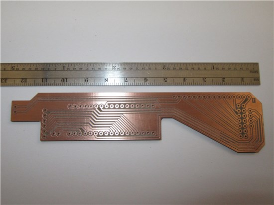
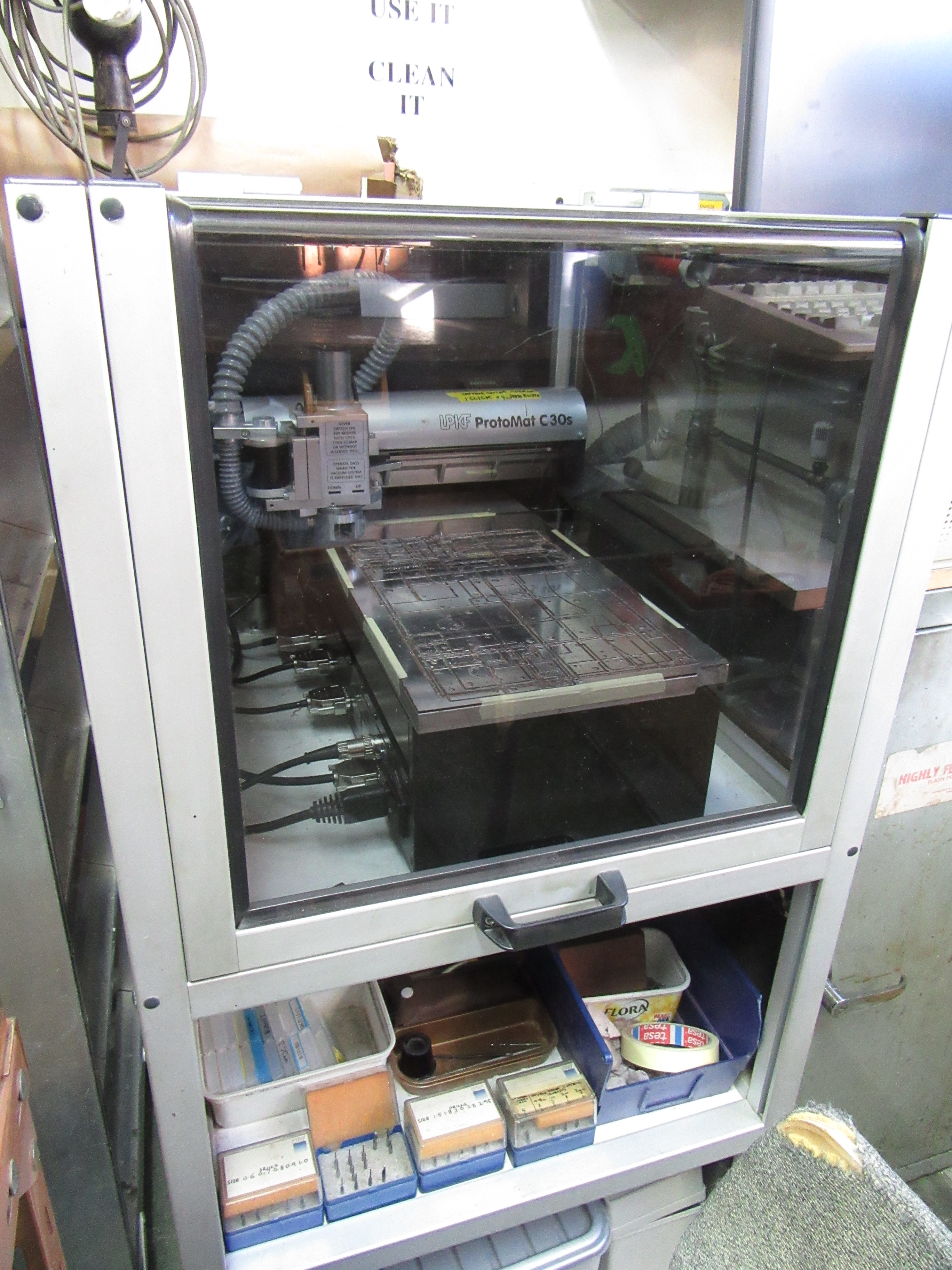 Our circuit board router is able to machine all of our single and double sided boards. This includes the drilling of holes, milling the gaps between tracks, and finally cutting out of the odd shaped boards (rectangular are available). Some awkward boards (such as small gaps between tracks) or large quantities are sent to an external company to produce. The only condition for our machine is that the gaps between tracks are >0.2mm wide and that the board is no bigger that the area of the table (200mm by 350mm). Some boards have needed large areas of the ground plane cut away for HV isolation or capacitance reduction. This is easy to achieve assuming that we design it onto the board in the CAD phase. We rarely require boards that have more than 2 layers, if we ever need to then we would go to an external company/separate department, however we can design them.
We have produced a few boards that have locating points, which then get handed to the mechanical workshop for some final work such as if the board needs a chamfered edge or a thin slot. A number of boards have also needed to slide into a rack system built by the workshop. The fact that we can hand them a board which we did not mind if it breaks is helpful, however, if the board is fully populated when it breaks, the person who breaks it may not be popular!
When we make a new board we like to stick it inside a box or case so that it is protected, and allows the user to connect to the circuit without fear of placing the unit onto a metal surface and causing damage through shorts. Dependant upon the circuit, then the case can also protect the user from injury through hot components or high voltages.
Some circuits also need to be setup or have controls set and then left untouched on the inside. This is easy to achieve with the boxes, we can either have a plate sticking up with the internal controls on, or have the controls on he circuit board. Some potentiometers can be installed such that the operator needs a screwdriver to operate. This reduces the chance of alteration, however, it means that the owner needs to know where such a screwdriver is located.
To achieve this, we have a stock of boxes on various sizes, and can order more or different sizes without much difficulty. Some of the boxes have front and back panels that can have things attached to. Others can have things attached to all 6 sides.
To get things looking as smart as they do, we have a small mill that we can use, and if we time it right, we can also borrow a lathe. Should the user request a large number of units, we can do one unit on our machine to work out were what goes, before sending the design through to the workshop to get lots made fast, assuming that they have sufficient time spare.
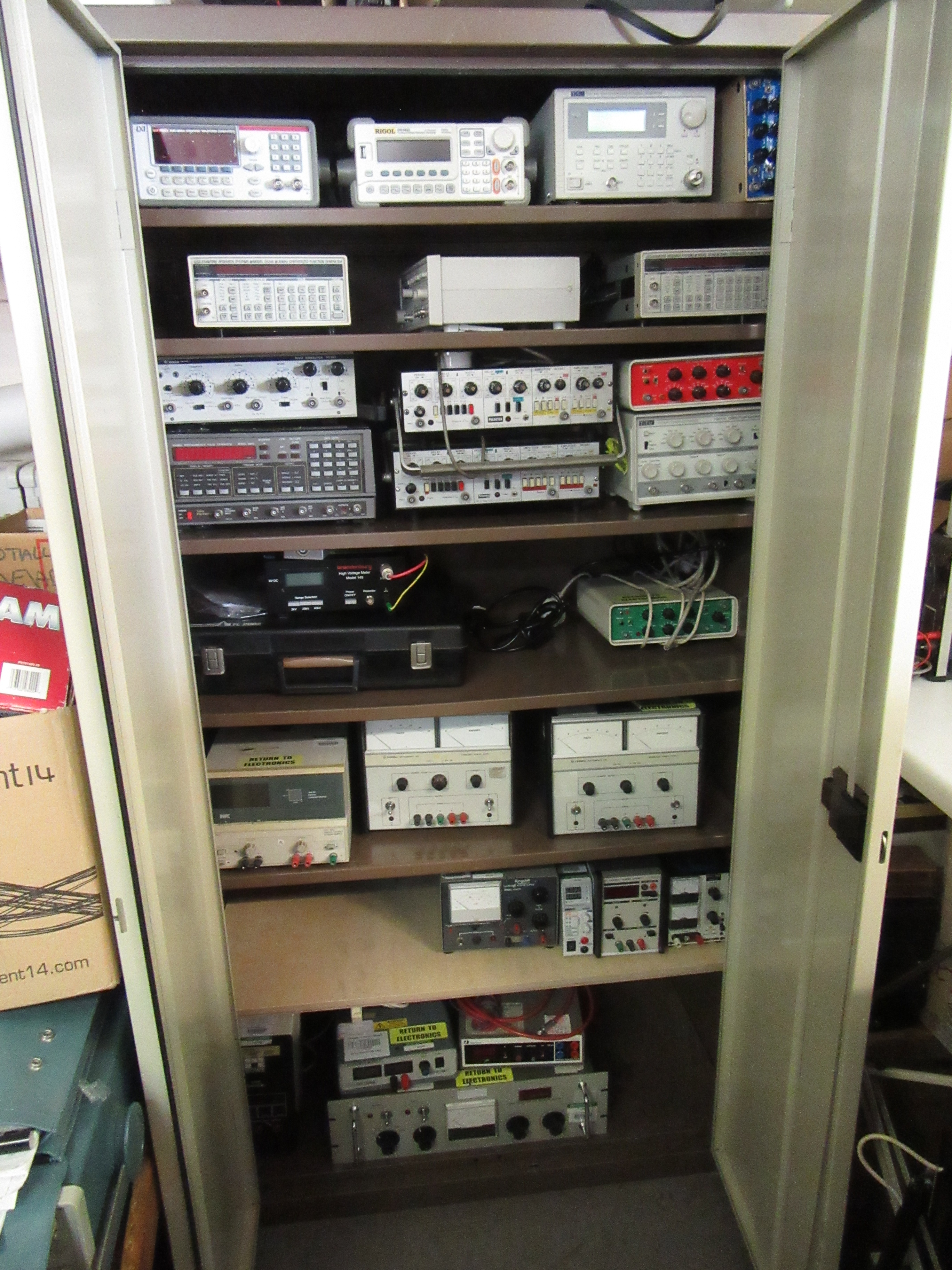 We have a stock of various test instruments that we can lend out for short periods of time (weeks, not years). The items include power supplies of various ratings, pulse generators, signal generators, a few amplifiers, and meters of various functionalities (see Loan items). We like to keep track of those items and be comfortable that user will not harm themselves or the units, so speak to us before taking anything.
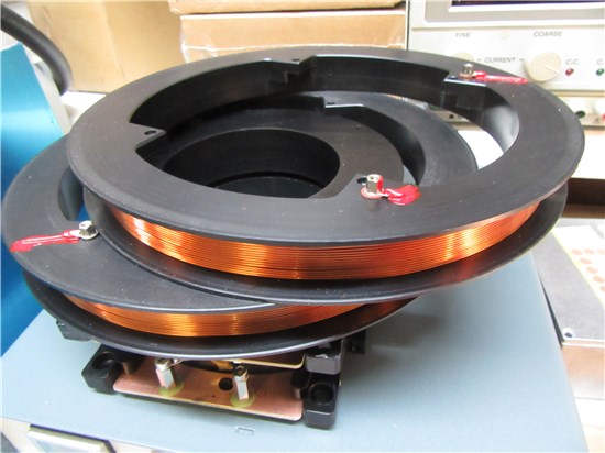 One facility that we have at our disposal, is a pair of coil winding machines. Those will wind coils of various sizes, also, allowing the operator to count (through a readout) how many turns they have put on. This enables them to accurately guess the magnetic field generated within the coil, and produce 2 identical coils therefore generate Helmholtz coils that have a uniform field, or in some cases no additional field in, therefore allowing for double bluff experimentation were needed. (see coils)
Some groups use electrodes for their electrochemistry.
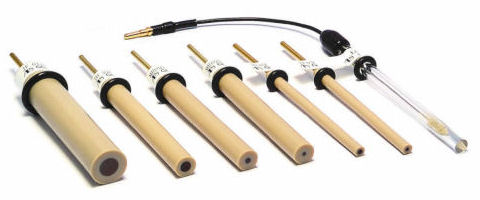 Those electrodes essentially connect a chemical solution to a pico-amplifier. This is achieved by having a piece of plastic or glass with a thin hole and some wire going through the hole. The solution connects to the wire at one end, and to a pin or length of loose wire at the other end.
If the electrode fails, it is typically where the length of loose wire joins the glass or plastic tube. On the plastic electrodes, this can be fixed, by basically cutting back a bit of the material and adding a support for the new wire which is re-soldered on. Where the insulating material is glass, then it may be fixable, it depends how close to the glass it brakes. This can be easier and quicker than getting a new electrode.
One issue with the electrochemistry is that it typically works better within a shielded box called a faraday cage. For some groups we (alongside the workshop) have made a box that the chemistry can sit in, and has heating (typically not cooling) and an air circulation device. The box itself produces a electromagnetic field free zone around the reaction assuming that the door of the cabinet is shut.
Most of the time this is either a reasonable sized box (400x400x600mm) which is ample for most experiments, or smaller versions around the 150x150x300mm size. Some have had special non-standard units that house the experiment in half of the unit, and have a second separated section that holds some control circuitry. The sections would be separated by a panel that is connected to the rest of the shielding, separating out the potentially noisy drive circuit from the experiment.
On some of our walls, yes, we do have walls, we have a large number of connectors and components including (but not limited to) resistors, capacitors digital gate chips and operational-amplifiers (op-amps). Those can be taken if you wish to do a small amount of circuit designing in the lab on breadboards. We stock the standard styles of chips used on breadboards (DIP6, DIP8 DIP14 and DIP16), and also have some adaptors to allow for more modern surface mountable chips to be used.
 When we make of leads and wish to cover up the join to reduce the chance of shorting, we cover it with some heat-shrink. This covers and will provide some protection to the joint from knocks and some breaks. We primarily have black and yellow heat-shrink. The stuff that we normally purchases has a shrink ration of 3:1 (it will try to shrink to about a third of its original size, however if the wire/component/unit within the unit is bigger than this smaller size, then the heat-shrink will stay at that size). This is satisfactory for most of out jobs. For the odd job, we do use adhesive heat-shrink which will stick to the cable after shrinking, as opposed from 'resting' on the surface. This means that it is harder to pull the joint apart, and gives any components within more water resistance.
Although we take every care to ensure the safety of you (the user), your colleagues, the equipment being used and the lab as a whole, we cannot ensure that you use the equipment as instructed.
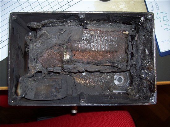 Therefore we provide experience to ensure that the specifications that you provide are within the working range of the equipment being provided. Should you provide us with inadequate information, then disaster can strike, such as with this high voltage switch (pictured left) where the user (who will remain nameless) tried to pulse the unit at too high frequency having been told what the specification was. This caused a catastrophic failure, but fortunately, no significant damage to the user or lab. The remnants are on display in the electronics cabinet of bangs. Other things are on display, so it is worth a visit.
top